background image


115 

232001840G(08)


NOTE 

This instruction is a simple example for general use. There are many tips and tricks to achieve a 
good engraving quality. It takes a lot of practice and experience to achieve a good engraving 
quality. Different picture may need different modifications and different material may need 
different parameters. 


Summary of Contents for LaserPro C180II

Page 1: ...232001840G 08 ...

Page 2: ...iented and safety in mind GCC understands that a creative technical background is the key to successful growth in the ever changing information economy We have a strong team of R D experts who propel our company to new heights From product development to manufacturing our engineers are dedicated to innovation and quality Guiding our solid technical base is a world class management team At GCC our ...

Page 3: ...Setup 27 4 1 2 1 Ethernet Connectivity Setup 30 4 2 Graphics Software Setup 36 4 2 1 Recommended Computer Configuration 36 4 2 2 Installation of the LaserPro Print Driver 37 4 2 3 Parallels Desktops for MAC Users 38 4 2 4 Using AutoCAD Inventor with GCC Lasers 43 4 2 7 Using eCut with GCC Lasers 45 Chapter 5 46 Operating the LaserPro C180II 46 5 1 Using the Hardware 47 5 1 1 Adjusting the LCD Disp...

Page 4: ...mb Table Option 121 7 4 Focal Lens Option 121 7 5 SmartAIR Nozzle Fine Ultra 122 7 6 SmartGUARD Fire Alarm Option 123 7 7 Rotary Attachment Option 125 Chapter 8 129 Basic Maintenance 129 8 1 Suggested Cleaning and Maintenance Supplies 130 8 2 Maintaining the Worktable and Motion System 131 8 2 1 Cleaning the Worktable and Motion System 131 8 2 2 Lubrication of the X Y Rails 131 8 3 Cleaning the Op...

Page 5: ...232001840G 08 Chapter 1 Safety Principles of CO2 Laser Safety Ratings The Safety Interlock System Safety Labels Safety Measures Operating Environment ...

Page 6: ...pen machine becomes Class 4 equipment and users must wear goggles to operate the machine 1 3 The Safety Interlock System The laser system is equipped with a safety interlock system utilizing magnetic sensors on the top and side access doors laser activation and door LED lights on the control panel The magnetic sensors will deactivate the laser when either door is opened At this time the door LED l...

Page 7: ...n Please familiarize yourself with the specific labels and their locations on the machine Below is a list of all the safety labels and their locations on the machine Product Label This label is located at the right back side of machine All the product information such as Serial Number Model Numbers Laser Power and Electric power can be found here Before requiring any tech support always provide se...

Page 8: ... equipment The following warning labels are placed on the laser system for your safety Do not remove these labels for any reason If the labels become damaged or have been removed for any reason do not operate the laser system and immediately contact Great Computer Cooperation or e mail us for a replacement Door open warning labels ...

Page 9: ...ser path Normally you can find this label inside of machine or laser exit Please take extra caution of this area when you conduct maintenance or operate machine Aperture warning stickers DANGEROUS VOLTAGES ARE PRESENT WITHIN THE ELECTRONICS ENCLOSURES OF THIS SYSTEM Access to these areas is not necessary during normal operation If it becomes necessary to open one of these enclosures for service re...

Page 10: ...surface or materials that may produce toxic substances or corrosion problems such as PVC and Teflon Laser Path Warning Label LaserPro machines are very safe under normal use Furthermore Laser Path Warning Labels are displayed at the proximities of possible laser paths as a reminder Operators should exercise caution when working close to these laser paths to avoid possible injury while machine is t...

Page 11: ...y of the machine Caution Use of controls or adjustments or performance of procedures other than those specified herein may result in hazardous radiation exposure GCC cannot be held responsible for any direct or indirect damages which result from using or working with the products electric circuits or software described herein The apparatus must be used only by trained and skilled personnel Before ...

Page 12: ...ck safety system Ensure the immediate work area of the machine is well ventilated Odors vapors and dust are by products generated during the laser engraving and cutting process An exhaust system vacuum cutting box and honeycomb table are recommended Please contact GCC or your local GCC distributor for more information Do not laser heat sensitive surfaces or materials that may generate toxic fumes ...

Page 13: ...the immediate area is functioning Setup the machine to be at least 60 cm 2 feet away from the wall NOTE SmartGUARD is an optional fire detection alarm system developed by GCC Contact your local GCC authorized distributor for more details for having this safety option installed onto your system 1 7 Noise Test Test Conditions measured at a distance of 1 meter from the surface of the machinery and a ...

Page 14: ...6 95 EC Low Voltage Directive 2004 108 EC EMC Directive Applied during design and construction of this product EN ISO12100 Safety of Machinery EN 60204 1 Safety of Machinery Electrical equipment of machines EN ISO 11553 1 for checking the Safety distances to prevent hazard zones being reached by upper and lower limbs of the Laser Engraver EN 60825 1 2007 Safety of laser products EN 60204 1 2006 AC...

Page 15: ...232001840G 08 15 Chapter 2 Unpacking Contents Unloading and Unpacking Contents and Accessories Checklist ...

Page 16: ...he shipping crate in order to avoid body injury or damage to the machine To prevent personal injury or damage to the machine please obtain assistance when loading and unloading the shipping crate NOTE Please save the original shipping crate If the machine must be returned for product servicing it will need to be packed in its original shipping crate Before unpacking the laser system make sure the ...

Page 17: ... 17 Unpack via the following steps 1 Move the shipping crate near the designated work area 2 Remove the packing tapes 3 Open the carton box 4 Carefully lift the machine out of the box with the help of another person ...

Page 18: ...o the top opening on the machine as shown in the picture below 2 Tighten the 2 thumb screws by hand and the air exhaust connecting box installation is complete 2 3 How to re pack the machine 1 Remove the exhaust connecting box from the machine and put the machine into the EPE foam first ...

Page 19: ... the machine with the plastic bag carefully and place onto the bottom EPE foam 3 Place the top EPE on the machine and place the exhaust connecting box on to the EPE Use tape to secure the slider on the exhaust connection box ...

Page 20: ...20 4 Place the machine into the package box 5 Cover the lid and tighten by rope ...

Page 21: ...tems are missing immediately contact your local GCC distributor ITEM QUANTITY Cleaning Kit Cotton Swab 1 Lens Cleaner Solution 1 Lens Tissue 1 PS2 Lubrication Grease 1 Main Power Cord 1 LAN Cable 1 USB Cable 1 CO2 Goggles 1 Focusing Tool 1 Exhaust Connecting Box 1 2 inch Exhaust Tubing 1 Installation CD LaserPro C180II user manual driver 1 Pencil Sample 2 Quality Promise Card 1 ...

Page 22: ...232001840G 06 Chapter 3 Mechanical Overview Front View Top View Right Profile View Left Profile View Rear View ...

Page 23: ... yourself with this section regarding the mechanical overview of the LaserPro C180II References will be made back to the different parts of the LaserPro C180II in later sections 3 1 Front View 3 2 Top View Lower Front Door Emergency Stop Control Panel ...

Page 24: ...232001840G 06 3 3 Right Profile View 3 4 Left Profile View Power Cable Inlet Printer Port Air Exhaust Adjustment Bar ...

Page 25: ...232001840G 08 3 5 Rear View USB Port Air Valve Ethernet Port Power Socket Laser Access Panel Fume Extraction Connection Port ...

Page 26: ...nstallation Machine Setup Powering Up the Machine Power Cable Connection Connecting the Computer Graphics Software Setup Recommended Computer Configuration Installation of the LaserPro USB Driver Installation of the LaserPro Print Driver ...

Page 27: ...computer through a USB Port or LAN Port connection interface Regardless of the connection method chosen you will need to connect the respective connection cable from the LaserPro C180II Series to your computer USB Connectivity Connect the included USB Port Cable to the USB Port on the right side of the LaserPro C180II Ethernet Connectivity Connect the LAN Cable in accessory to the LAN port on the ...

Page 28: ...chine Setting Æ LAN Setup Wizard Æ IP Address Step 3 Go to Windows Control Panel Æ Hardware and Sound Æ Printer and right click on Spirit series printer to check printer properties Step 4 Go to Ports tab of printer properties and select Add Port and follow the instruction to enter the TCP IP information received from laser machine control panel in step 2 ...

Page 29: ...232001840G 08 ...

Page 30: ...AN port of GCC laser engravers and turn on machine Step 2 Navigate the control panel through F4 FunctionÆ Machine Setting Æ LAN Setup Wizard Æ DHCP OFF Step 3 Navigate the control panel through F4 FunctionÆ Machine Setting Æ LAN Setup Wizard Æ IP Address Step 4 Enter 192 168 3 X X refers to 1 255 value which can t be the same value with IP address setting in PC or Notebook for IP and 255 255 255 0...

Page 31: ...PanelÆNetwork and InternetÆNetwork Connections of computer right click mouse on the connected internet device and choose Properties Step 6 Choose the Internet Protocol Version 4 TCP IPv4 and click Properties to open up the setting window ...

Page 32: ... and choose OK Note the IP address 192 168 3 X X value can be 1 255 while can t be the same number as machine control panel setting in step 4 Step 8 Go to Control Panel Æ Device and Printers of computer and right click on the laser machine printer choose Printer Properties ...

Page 33: ...232001840G 08 Step 9 Select Add Pot under Ports tab and follow the instruction to enter the TCP IP information in laser machine s control panel in step 4 ...

Page 34: ...232001840G 06 ...

Page 35: ...232001840G 08 ...

Page 36: ...s under Windows operating systems and is designed to work on a computer that meets the following minimum requirements Computer Compatibility CPU Pentium 90 or equivalent or greater RAM 32MB or higher HDD 1 2 GB Hard Drive or greater SVGA 15 Super VGA Monitor On Board Parallel Mode Enabled from your motherboard s BIOS SPP Preferred Mode ECP Cable Less than 1 8 meters Software Compatibility The Lase...

Page 37: ...ue 8 If a screen comes up informing you of the detection of a previous driver and asks to keep the existing driver or use the new one select Replace Existing Driver and click Next to continue 9 This screen will prompt you to provide a printer name Simply type in C180II and select Yes or No if you want to use this printer as the default printer and click Next to continue NOTE When working with the ...

Page 38: ... software which allows you to install Windows OS in MAC computers and run Windows based software under MAC computer and output with GCC print driver 1 Purchase Parallels Desktops on its official website 2 Install Parallels Desktops under Mac OS environment 3 Read Software License Agreement and press Accept to continue installation ...

Page 39: ...39 232001840G 08 4 Enter your Mac OS X User Name and Password then press OK 5 Press Active 6 Press OK when activation is complete ...

Page 40: ...sktop 8 Press Register and OK to complete the installation of Parallels Desktop 9 Open Parallels Desktop in the Applications folder then choose File New 10 Press Install Windows from DVD or image file then press continue to install windows OS ...

Page 41: ...41 232001840G 08 11 Select CD ROM drive with the Windows installation CD 12 Enter the Windows OS product key ...

Page 42: ... is complete the windows OS installation procedure will start automatically 15 Windows OS installation is complete then you can refer to 4 2 4 Installation of the LaserPro Print Driver to install GCC LaserPro Print Driver 16 Install the AP that you want to use after the above installation is complete ...

Page 43: ...ntor with GCC Lasers 1 Start drawing 2 Delete border and title block by right clicking on sheet1 and selecting delete 3 Set sheet size to match working area of engraver Engraver working area can be found on the paper tab of the windows driver ...

Page 44: ... Start sketch 5 Engraving a Finish sketch b Right click on sketch and select properties c Line Type By Layer d Line Weight By Layer e Set color to match one of the 16 colors available in the pen tab of the windows driver ...

Page 45: ...ations workflow eCut details and operation videos can be found on http eng e cut ru eCut unique feature list y Nesting y Puzzles y Material usage calculation y AutoText to import files including image text QR code and barcode etc to the linked variable columns y Slice Tile function y CAD editing function y Sign box and packaging box aided design y 2D barcode y QR code NOTE All objects created in o...

Page 46: ...l Panel Function Pages The LaserPro C180II Print Driver Page Setup and Orientation Color Management Using the LaserPro C180II Print Driver LaserPro C180II Print Driver Options Page LaserPro C180II Print Driver Pen Page LaserPro C180II Print Driver Advanced Page LaserPro C180II Print Driver Paper Page LaserPro C180II Print Driver Language Page LaserPro C180II Print Driver Raster Page LaserPro C180I...

Page 47: ...ghting of your immediate work area you may need to adjust the LCD display screen s contrast You may increase or decrease the display screen s contrast via the contrast adjustment wheel found on the inside of the front cover on the bottom right side You can access this area by opening the top window and looking inside to the near right side of the work area as shown in the picture below 5 1 2 Graph...

Page 48: ...conds warm up time Directional and Selection Buttons Function F1 F2 F3 F4 Four function buttons allow you to select various functions which will change depending on what section of the menu you are in Each function button s corresponding task will be displayed right above its respective button on the LCD display screen Please note that in certain menus not every function button will always be mapp...

Page 49: ...ocus Command Mode Carriage Free File Save Mode LAN Setup Wizard Functions Page File Information Page Other Advanced Option Page Reset SmartGUARD Vector Mode LED light Setting and the material you can use the S T buttons to do so Doing so will adjust the vertical height z axis of the worktable 5 1 3 Graphic Control Panel Navigation Chart ...

Page 50: ...ions of the control panel This will be the page that is displayed when you are processing your jobs This page contains specific job information such as the current job s name Speed Power PPI DPI processing remaining times and jobs loaded Main Work Page Relevant Buttons Function F1 Prev Scroll through previous jobs F2 Next Scroll through next jobs F3 SP Go to Store Position Page for SmartCENTER F4 ...

Page 51: ... X axis of the laser carriage Carriage Work Table Adjustment Page Relevant Buttons Function F1 Back Back to previous page F3 Down Manually decrease the height of the work table Z axis F4 Up Manually increase the height of the work table Z axis U V Y Z Directional Manually adjust the Y axis position of the laser carriage Y Z Directional Manually adjust the X axis position of the laser carriage Star...

Page 52: ...utton You will be prompted to indicate and store the position points The positions can be indicated by moving the carriage by hand and pressing enter to save the positions indicated by the red pointer After all points are set the carriage will move to the center of the stored positions and the job will begin SmartCENTER Page Relevant Buttons Function F1 Back Back to previous page F2 Reset Reset al...

Page 53: ... File Save Mode Set Vector Mode Tune Image Power Set Laser Wattage Set Fine Mode Other Reset Machine Information Page this page allows you to view information regarding the system such as the GCC logo machine name firmware version and other information Functions Page Relevant Buttons Function F1 Back Back to previous page F3 Help Display help F4 Recall Back to previous page U V Directional Scroll ...

Page 54: ...ng File Management Page Relevant Buttons Function F1 Back Back to previous page F2 Link Display help F3 D All Back to previous page F4 Del Delete the selected job U V Directional Scroll through the menu selections Enter Perform the selection Start Stop Back to Main Work Page Auto Focus Initiate the auto focus function S T Manual Focus Buttons Manually adjust the height of the work table Z axis Mai...

Page 55: ...quence The second column after the file name displays that job s next file in the job queue sequence First and last jobs in the job sequence you set will have a in the first and second columns respectively So according to the image above the job queue sequence has been set to be processed in this order 03 Marble cdr J 01 Marble cdr J 02 Marble cdr Link DLink Page Relevant Buttons Function F1 Back ...

Page 56: ...ected job File Information Page Relevant Buttons Function F1 Back Back to previous page F4 Edit Go to the File Management Edit Page for the selected job Start Stop Back to Main Work Page Auto Focus Initiate the auto focus function S T Manual Focus Buttons Manually adjust the height of the work table Z axis Main Work Page Functions Page Navigating to this page press F4 File Management Page Select F...

Page 57: ...ck to previous page U V Directional Scroll through your loaded jobs Y Z Directional Cycle through the available selections Enter Perform the selection Start Stop Back to Main Work Page Auto Focus Initiate the auto focus function S T Manual Focus Buttons Manually adjust the height of the work table Z axis Main Work Page Functions Page Navigating to this page press F4 File Management Page Select Fil...

Page 58: ...r Power 0 0 100 Raster Speed 0 1 100 SmartACT YES NO File Edit Raster Page Relevant Buttons Function F1 Back Back to previous page U V Directional Scroll through your loaded jobs Y Z Directional Cycle through the available selections Start Stop Back to Main Work Page Auto Focus Initiate the auto focus function S T Manual Focus Buttons Manually adjust the height of the work table Z axis Main Work P...

Page 59: ...0 100 Vector Speed 0 0 100 Vector PPI 30 1524 Power Ramp YES NO File Edit Vector Page Relevant Buttons Function F1 Back Back to previous page F4 Save Save your current settings U V Directional Scroll through your loaded jobs Y Z Directional Adjust the value for that selection Start Stop Back to Main Work Page Auto Focus Initiate the auto focus function S T Manual Focus Buttons Manually adjust the ...

Page 60: ...Reset Machine Setting Page Relevant Buttons Function F1 Back Back to previous page U V Directional Scroll through your loaded jobs Enter Perform the selection Start Stop Back to Main Work Page Auto Focus Initiate the auto focus function S T Manual Focus Buttons Manually adjust the height of the work table Z axis Main Work Page Functions Page Navigating to this page press F4 Machine Setting Page Se...

Page 61: ...ns The LaserPro C180II default setting is 2 0 Lens 1 5 2 0 Set Lens Page Relevant Buttons Function F1 Back Back to previous page F4 Save Save your current settings U V Directional Cycle through selections Start Stop Back to Main Work Page Auto Focus Initiate the auto focus function S T Manual Focus Buttons Manually adjust the height of the work table Z axis Main Work Page Functions Page Navigating...

Page 62: ... Back to previous page F4 Save Save your current settings U V Directional Manually adjust the height of the work table Z axis Start Stop Back to Main Work Page Auto Focus Initiate the auto focus function S T Manual Focus Buttons Manually adjust the height of the work table Z axis Navigating to this page Main Work Page Functions Page press F4 Machine Setting Page Select Machine Setting from the Tun...

Page 63: ...hen the LaserPro C180II will not display this warning prompt at system startup Table Down YES NO Distance 0 165 mm Set Table Down Page Relevant Buttons Function F1 Back Back to previous page F4 Save Save your current settings U V Directional Scroll through the menu selections Y Z Directional Adjust the value for that selection Start Stop Back to Main Work Page Auto Focus Initiate the auto focus fu...

Page 64: ... laser carriage and movement or positioning can only be done by the control panel Carriage Free YES NO Carriage Free Page Relevant Buttons Function F1 Back Back to previous page F4 Save Save your current settings Start Stop Back to Main Work Page Auto Focus Initiate the auto focus function S T Manual Focus Buttons Manually adjust the height of the work table Z axis Navigating to this page Main Wor...

Page 65: ...th output formats are supported Mode Default HPGL Vector Pen 1 16 Vector Speed 0 0 100 Vector PPI 0 0 100 Power Ramp YES NO Set Command Mode Page Relevant Buttons Function F1 Back Back to previous page F4 Save Save your current settings U V Directional Scroll through the menu selections Y Z Directional Adjust the value for that selection Start Stop Back to Main Work Page Auto Focus Initiate the au...

Page 66: ...in all job files on the LaserPro C180II File Save YES NO File Save Mode Page Relevant Buttons Function F1 Back Back to previous page F4 Save Save your current settings Y Z Directional Cycle File Save between YES NO Start Stop Back to Main Work Page Auto Focus Initiate the auto focus function S T Manual Focus Buttons Manually adjust the height of the work table Z axis Navigating to this page Main W...

Page 67: ...o apply static IP address and you need to further enter the IP address MASK and GATE information Using Left or Right directional keys under dynamic IP setting page to scroll between different columns to enter the address and use Up or Down keys to change the numbers DHCP NO OFF Please refer to Chapter 5 2 1 for ethernet connectivity setup in Windows driver Navigating to this page Main Work Page Fu...

Page 68: ... Y Z Directional Cycle DHCP between NO OFF or move between tabs on IP address settings U V Directional Scroll between menu options or change the numbers of IP address settings Start Stop Back to Main Work Page Auto Focus Initiate the auto focus function S T Manual Focus Buttons Manually adjust the height of the work table Z axis ...

Page 69: ... previous page F4 Save Save your current settings Y Z Directional Adjust the X axis scaling numbers U V Directional Adjust the Y axis scaling numbers Start Stop Back to Main Work Page Auto Focus Initiate the auto focus function S T Manual Focus Buttons Manually adjust the height of the work table Z axis Navigating to this page Main Work Page Functions Page press F4 Machine Setting Page Select Mach...

Page 70: ...ENGLISH others dependent on Firmware Unit METRIC ENGLISH EOF Alarm YES NO Air Delay 1 100 seconds Tip Depending on the material you are engraving with your laser settings and the desired results please experiment with the air delay to achieve your desired results Others Page Relevant Buttons Function F1 Back Back to previous page F4 Save Save your current settings U V Directional Scroll through th...

Page 71: ... previous page U V Directional Scroll through the menu selections Enter Perform the selection Start Stop Back to Main Work Page Auto Focus Initiate the auto focus function S T Manual Focus Buttons Manually adjust the height of the work table Z axis Navigating to this page Main Work Page Functions Page press F4 Machine Setting Page Select Machine Setting from the menu Others Page Select Others from...

Page 72: ...ler objects positioned away from the default start position top left of the work table Recall Position To recall the saved position simply go to Functions page and press F4 again to recall the saved position The laser carriage will be moved to the saved position Main Work Page Functions Page Navigating to this page press F4 Select Recall by pressing F4 Navigating to this page Main Work Page Functi...

Page 73: ...ically stop laser firing For example if the sensor delay switch is set to the 3 second position the SmartGUARD will start an alarm and automatically stop laser firing after detecting a fire for 3 seconds Stow Carriage烉 This function will decide if the lens carriage stay in the last position set to NO or move to the opposite direction up or down when fire alarm is initiated The default is YES the l...

Page 74: ...rPro C180II default setting is Fine Vector Modes Quality Production Speedy Slower speeds higher quality Faster speeds lower quality Vector Mode Page Relevant Buttons Function F1 Back Back to previous page F4 Save Save your current settings Y Z Directional Cycle Set Vector Mode between QUALITY VECTOR FINEVECTOR COARSE VECTOR SPEEDY VECTOR Start Stop Back to Main Work Page Auto Focus Initiate the au...

Page 75: ...e Relevant Buttons Function F1 Back Back to previous page U V Directional Scroll through the menu selections Enter Perform the selection Start Stop Back to Main Work Page Auto Focus Initiate the auto focus function S T Manual Focus Buttons Manually adjust the height of the work table Z axis Main Work Page Functions Page Navigating to this page press F4 Machine Setting Information Page Select Infor...

Page 76: ...you may set it up through the graphics software as well The following is taking Corel Draw as example of how to set up LaserPro C180II as the Printer 1 From the primary menu click FILE PRINT SETUP 2 From the navigation bar Name click C180II OK 5 2 1 Page Setup and Orientation The first thing you must do before working with the LaserPro C180II Print Driver will be to make sure the page and layout s...

Page 77: ...t click DOCUMENT PAGE SIZE 5 Ensure that NORMAL PAPER and LANDSCAPE are selected 6 Ensure the Paper Width and Height dimensions match the LaserPro C180II s work table dimensions of 458 mm 18 inches and 305 mm 12 inches 7 Click OK to complete the paper size adjustment Tip Instead of manually selecting the Landscape and setting the Paper Width and Height you can simply click the Set From Printer fun...

Page 78: ...re used for this example For other graphics software you will need to access the corresponding Color Management page 1 From the primary menu click TOOLS COLOR MANAGEMENT and CorelDRAW s Color Management will appear 2 Under the Style pull down menu select COLOR MANAGEMENT OFF 3 Click OK to complete the color management adjustments 5 2 3 Using the LaserPro C180II Print Driver Now after you have prop...

Page 79: ...Raster Page appears only in Black White Mode Stamp Page appears only in Stamp Mode Tip The following sections describe the specific functions for each of the settings ound in the LaserPro C180II Print Driver If you are new to laser engraving it is recommended that you first familiar yourself with the general principals of the laser process in Chapter 6 especially the Vector Cutting and Raster Engr...

Page 80: ... Please refer to the next section of the manual for details regarding the PEN functions The LaserPro C180II print driver will interpret colored and shaded areas as different shades of gray by producing a halftone effect while engraving Instead of engraving only solid lines gray halftone areas will be a collection of dots with varying density The resolution and depth of these halftone areas can be ...

Page 81: ...ps Stamp Mode Select this mode when you would like to engrave stamps The stamp mode is one of the more dynamic functions of the LaserPro C180II Series by applying 200 power levels to create different steps Due to the unique engraving nature when engraving a stamp the stamp production requires different operational steps than most engraving or cutting operations NOTE Selecting the Stamp mode will e...

Page 82: ...d vice versa The Invert option is not available in disabled with Manual Color File mode selected Print Immediately Option Page DEFAULT SETTING Unselected Checking this will instruct the LaserPro C180II to immediately begin the laser engraving process when you select Print from your graphic software program If Print Immediately is not checked then selecting Print will transfer the job file to the L...

Page 83: ...the SmartACT optimization modifies the movement of the X axis of the lens carriage Preview Options Page DEFAULT SETTING Unselected Users can use the Preview function to check a simulated output of the job An estimated working time will also be shown Please make sure to set the file printing option to print to file in order to activate the Preview function A filename will be prompted ...

Page 84: ...of the recent files you have recently created and worked SAVE This function will save current print driver parameter settings to a file under the specified location on your computer Saved parameter setting files will be tagged with the C180II extension LOAD This function allows you load a previously saved print driver parameters ORIGINAL This function will load the print driver s original factory ...

Page 85: ...Tip LaserPro material database settings allow you easy to load the several parameters If you are loading LaserPro parameter database as your operating parameter please direct load from several build in parameter folders ...

Page 86: ...signated laser setting rather than as a color As an example a black and white image will use only one power and speed laser setting Black An image that is made up of black red and blue colors will be processed using the laser settings designated for each particular color In order to utilize up to 16 different pens laser parameter settings make sure your graphics software can recognize and utilizes...

Page 87: ...t define custom colors to define your own color shown in the picture below This is useful when your image is composed of colors that are not part of the pen menu s default color selection and instead of modifying your image you simply would like to assign the laser settings based on the existing colors based on your current image NOTE The LaserPro C180II print driver cannot store more than 16 pen ...

Page 88: ...ower will produce deeper cuts and engravings whereas higher speeds at lower power will produce more shallow cuts and engravings PPI Pen Page DEFAULT SETTING 400 PPI pulses per inch represents the pulsing frequency of the laser pulse fire numbers within an inch exclusive for vector cutting Higher PPI settings may cause more melting burning or charring on the edges when cutting Lower PPI settings ma...

Page 89: ... if you have the optional air compressor installed By selecting a pen color and checking this box will enable the SmartAIR air assist function for that particular pen color As an example if you are performing a combination of both surface raster engraving job and deep vector cutting on a material such as acrylic you may want to enable the SmartAIR air assist for the vector cutting sections to get ...

Page 90: ...ign setting Position Modes Advance Page DEFAULT SETTING Home These selections allow you to control the positioning of the laser head after each job completion and before the next subsequent job Home Resets the positioning of the laser head to the home position upper right before and after each job Without Home The laser head will start the next job based on its position from its graphic applicatio...

Page 91: ... to front end of the work table Bottom To Top Selecting this will force the system to process the current task by moving the laser carriage from the bottom to the top of the image front end to rear end of the work table Normally the LaserPro C180II engraves from left to right top to bottom Selecting Bottom Up will force the machine to start from the bottom and work its way to the rear of the worki...

Page 92: ...broken down and isolated from each other areas not touching each other blank space in between Another condition that must be met for the Cluster function is that these individual areas of your design must have some X axis overlap meaning that they should be somewhat side by side with empty space between them The distance value can be set by the user and represents the limit or cutoff point in whic...

Page 93: ...output sequence and by doing so masking the banding problems This feature is only suitable for engraving large sized graphics Note The overall working time will be increased True Image is a function that will shuffle the normal engraving sequence to produces a nicer engraving output by reducing possible banding occurrences 5 2 3 4 C180II Print Driver Paper Page ...

Page 94: ... sample and apply a magnifying glass to the engraved results When you look at your engraved test square under a magnifying glass you may notice the edges of your square may be slightly offset with every consecutive engraved even or odd line protruding past the square s ideal edge This occurrence may occur on the left or right side of the square and can be compensated for by the image tuning settin...

Page 95: ...re function and notice the change in the Paper Size fields Under Paper Size the X value represents the length of your work piece Enter the length of your work piece in this field 2 Under Paper Size the Diameter value represents the diameter of your working piece at the position you wish to engrave Enter the diameter of your work piece in this field Again remember the proper diameter value would be...

Page 96: ...0II Print Driver Language Page This page allows you to specify the language displayed by the C180II Print Driver Available language options include English Spanish French Japanese German Simplified Chinese and Traditional Chinese ...

Page 97: ...uick and easy way to immediately adjust the contrast of an engraved image Moving the slider to the Dark setting will increase the contrast levels of the engraved output whereas moving the slider to the Light setting will decrease the contrast levels of the engraved output Tip There are other ways to adjust an engraved image s contrast such as adjust the power speed settings or simply adjusting the...

Page 98: ...rn Type selected DEFAULT SETTING 8 x 8 This controls the resolution dot size and the number of dots the image is broken down into for the dithering process As an example selecting 2 x 2 will shade with a 5 grade halftone where as an 8 x 8 Dithering Matrix will dither with a 65 grade halftone The following diagram is an example of the raster effects when using the different dithering matrices 2 x 2...

Page 99: ...opriate settings will be based on a variety of factors your design the material you are engraving on the results you wish to achieve etc Please take some time to experiment with the multitude of raster options to get the one you feel is the best for your piece This is where much of the fun in engraving is experimentation ...

Page 100: ... Stamp Page Your stamp will be a reversed image composed of engraved depressions and ridges Think of these ridges as the contact sections of the stamp If the ridges of these contact sections are too thin they may break The Pitch setting allows you to increase the width of the ridge base hence creating more stable contact sections and longer lasting stamp The pitch value setting allows you to adjus...

Page 101: ...his function allows you to adjust the slope for the shoulder sections of your stamp By sliding the sliders or directly input of power levels you will be able to change the slope of the shoulder NOTE The visual representations of the Pitch and Shoulder Levels in the C180II driver are an exaggerated representation to allow for easy visual guidance and precise input Remember we are working with dista...

Page 102: ...102 232001840G 08 Chapter 6 Engraving and Cutting Techniques Raster Engraving Vector Cutting Vector and Raster 3D Tips To Modified Image Settings of a Picture for Better Engraving Quality ...

Page 103: ...raster engraved piece would be a photo engraving on tile as shown in the picture below 6 2 Vector Cutting A laser engraver can process text design and images composed of lines through continuous firing of the laser to cut out various shapes When performing vector cutting operations imagine the laser head as a pair of scissors cutting out the lines specified in your design An example of a vector cu...

Page 104: ...cted characters outline thickness to the thinnest width by right clicking on the selected text select Properties Click on the Outline tab and change the Width to its thinnest dimension Click on OK to apply the changes 5 Now your string of characters has been properly designated as an area to be vector cut Simply print your job output the file to the C180II and watch as your string of characters is...

Page 105: ...oduction Many ways to produce 3D graphics are available If you are familiar with or frequently use one of the 3D software in the market like Laser Type EngraveLab 3D Studio etc you may use it for the production of 3D graphics After completion save the 3D images as one of the formats that is compatible with the Laser Engraver such as JPG or BMP and let the machine begin the engraving If you are not...

Page 106: ...n Then you may output the 3D graphic to the laser for the production of the 3D object Take the figure below as an example After producing two graphs in gray level proceed with the arrangement and combination Then you may let the laser proceed with 3D mode Both Photoshop and CorelDRAW may produce 3D graphics in the manner of combination A way to produce 3D graphics For the production of 3D graphics...

Page 107: ...107 232001840G 08 ...

Page 108: ...sts your attention If you need to produce circular 3D graphics you only need to select Radial as the gray level type in the pull down menu of Type Then a circular 3D graphic may be produced Step 2 Produce three dimensional characters ...

Page 109: ...109 232001840G 08 ...

Page 110: ...e production for each of the objects you may proceed with the combination of the objects The combined graphic may be output with the laser engraver Output the 3D graphic After selecting the graphic to be output set the Mode as 3D Mode in the driver After setting the engraving parameters output the 3D graphic ...

Page 111: ...ngraving would be deeper Set Air assist inside the driver by checking the box Polish Dust will accumulate during the engraving when acrylic is engraved The acrylic may be polished with Polish after the engraving After the processing don t remove the engraved object Use the Control Panel to lower the platform for about 7 8 mm and then engrave once again to achieve the better finish After engraving ...

Page 112: ...to the computer by USB cable 2 Download the picture from the digital camera to the computer 3 Select the picture that you want to engrave 4 Import the image from the folder where the picture is located by selecting File Import 5 Convert the image to Bitmap by selecting the image and click on Bitmaps Convert to Bitmap ...

Page 113: ...113 232001840G 08 6 Change the Bitmap settings by setting Color to Grayscale 8 bit and Resolution to 300 dpi and click OK 7 Finally Invert the image by selecting Effects Transform Invert ...

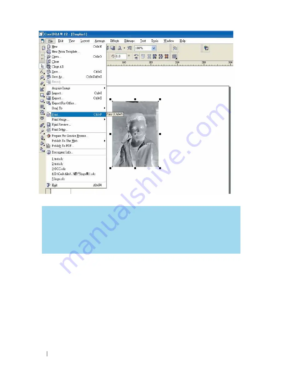
Page 114: ...114 232001840G 08 8 Now you are ready to output the modified image by clicking File Print ...

Page 115: ...or general use There are many tips and tricks to achieve a good engraving quality It takes a lot of practice and experience to achieve a good engraving quality Different picture may need different modifications and different material may need different parameters ...

Page 116: ...840G 08 Chapter 7 Optional Items Fume Extraction System Option Air Compressor Option Items Honeycomb Table Option Focus Lens Option SmartAIR Nozzle Fine Ultra SmartGUARD Fire Alarm Option Rotary Attachment Option ...

Page 117: ...y are but a few outstanding features Each LaserPro Fume Extraction System is powered by a maintenance free continuous running turbine In order to ensure personnel safety and legal compliance the LaserPro Fume Extraction System is CE compliant To purchase a LaserPro Fume Extraction System contact your local authorized GCC distributor 7 1 1 INSTALLATION Self Assembled Unit 1 Purchase an exhaust syst...

Page 118: ... bar to the right side the Top Suction will increase User can adjust the bar according to the application The top ductwork is suitable for dust smoke generated on material surface when doing laser engraving which will reduce residue left on material surface while the bottom ductwork is recommended for laser cutting jobs Optimum down vacuum is critical for clear cutting edge when laser cutting mate...

Page 119: ...dition the air compressor provides the optimal air flow to the SmartAIR nozzles to minimize flaming suppress working temperatures and blow away dust and particle byproducts generated from the laser process Power Cord B 1 4 Air Inlet Tubing Power Cord A INSTALLATION 1 Remove the plugs on the air compressor to expose the air inlets 2 Fasten the included air tube fastener valve to the outgoing air in...

Page 120: ...male end to an external power outlet Congratulations you have finished setting up the air compressor Make sure you have the proper SmartAIR nozzle installed depending on your application before you turn on and utilize the air compressor OPERATION Switch on the air compressor unit and make sure that the airflow regulator on the air assist valve is opened turn clockwise to increase the airflow count...

Page 121: ...eam passes through a 2 0 focus lens the beam will converge at a 2 0 distance resulting in a concentration of energy at that spot The resulting spot size from the different focus lens are also different and the following chart shows the different spot sizes achieved from the different lenses y 1 5 Lens The 1 5 lens is best when used for engraving of very fine details y 2 0 Lens The 2 0 lenses are g...

Page 122: ...tioned closer to the object for a concentrated blast directed over a small area to eliminate burning on the cutting edge The perfectly vertical design of the SmartAIR Fine Nozzle pro duces a concentrated airflow to blow away dust and unwanted residue leaving a clean product surface The Ultra Nozzle is recommended for the need of even stronger airflow for applications such as deep cutting ...

Page 123: ...n the laser firing as a safety precaution Note that SmartGUARD fire alarm is an fire detecting and alarm system not a fire extinguisher INSTALLATION If you have purchased your system with SmartGUARD then no installation is required as your system will arrive with SmartGUARD pre installed For system owners that did not initially purchase this option but would now like to add the SmartGUARD they wil...

Page 124: ...gs 1 3 5 7 9 seconds that can be selected Sensitivity defines the time from when a fire is detected until the fire alarm alerts user of fire and automatically shuts down the laser from firing For example if the sensor delays switch is set to the 3 second position the SmartGUARD will start an alarm and automatically stop laser firing after detecting a fire for 3 seconds Navigating to this page Main...

Page 125: ... allow for engraving on cups wine glasses and even spherical objects Work Piece Limitations Model C180II Maximum Length 250 mm 9 8 inches Maximum Loading Weight 3kg 6 lbs Minimum Inner Diameter Small conical fixture 12 mm 0 47 inches Maximum Inner Diameter Small conical fixture 46 mm 1 8 inches Minimum Inner Diameter Large conical fixture 50 mm 1 9 inches Maximum Inner Diameter Large conical fixtu...

Page 126: ...ide the LaserPro C180II shown in the picture below 7 Close the front door panel Rotary Attachment Port 8 The rotary attachment is now properly installed Power on the LaserPro C180II and the rotary attachment will be automatically detected and the engraving table will automatically move to its lowest position OPERATION 1 Use a ruler to measure the diameter at the point on the work piece you will be...

Page 127: ...the position you wish to engrave Enter the diameter of your work piece in this field Again remember the proper diameter value would be the diameter location on your work piece you will be engraving c Under Rotary Parameter the Offset value represents distance from the open end of your work piece to the base of the padded rubber wheel This value will be displayed on the LCD panel Enter the proper o...

Page 128: ...ller conical fixture onto the rotary attachment as shown below D Use the flat surface as shown in picture below as a reference point and tighten the first screw against it After doing so tighten the second screw and the rotary attachment is ready for use Flat surface 1 Tighten this against the flat surface 2 Tighten the second screw ...

Page 129: ...ed Cleaning and Maintenance Supplies Maintaining the Work table and Motion System Cleaning the Work table and Motion System Lubrication of the Rails Cleaning the Optics System Removing the Mirrors Cleaning the Mirrors Removing and Cleaning the Focal Lens ...

Page 130: ...system if you do not turn off and unplug the C180II before cleaning Always turn off and unplug the LaserPro C180II before cleaning Resulting debris from laser cutting are very dangerous and may cause fire hazard 8 1 Suggested Cleaning and Maintenance Supplies Cleaning Maintenance Tool Special notes Soap Solution or All Purpose Cleaner Paper Towels Cotton Cloth Denatured Alcohol DO NOT use alcohol ...

Page 131: ... operating the C180II CAUTION Never pour or spray alcohol or acetone directly to the working table Oil alcohol and acetone can cause fires or smoke build up if improperly used TIP Please clean the AutoFocus pin each time after completing the engraved job to make sure the AutoFocus pin is free to move 8 2 2 Lubrication of the X Y Rails In order to keep the motion system running smoothly the X Y rai...

Page 132: ...the mirrors The following section will detail how to access and remove each of the four mirrors found on the LaserPro C180II for cleaning Mirror 1 This mirror is located inside the bottom cover of the LaserPro C180II 1 Use a Screwdriver to remove the back cover located on the bottom side of the LaserPro C180II 2 Loosen the thumbscrew and screw to the dust cover securing the mirror As shown in the ...

Page 133: ... and remove the black dust cover covering mirror 2 2 Unscrew the thumbscrew holding mirror 2 in place 3 Clean the lens in the proper manner 4 Re install mirror 2 after cleaning 5 Tighten the thumbscrew 6 Replace and secure the dust cover ...

Page 134: ...n the lens in the proper manner 3 Re install mirror 3 after cleaning 4 Tighten the thumbscrew Mirror 4 1 Unscrew the three thumbscrews front face of the laser head securing the laser carriage panel and remove the laser carriage panel to reveal mirror 4 and the focal lens 2 Loosen the top thumbscrew to remove mirror 4 as shown in the picture below Top Thumbscrew Mirror3 ...

Page 135: ...without touching the reflective side of the mirror DO NOT apply any finger pressure or any other cleaning solutions to the mirror surface 2 Drape a new sheet of lens tissue over the mirror 3 Apply a few drops of lens cleaner on the tissue covered mirror apply enough so that the tissue absorbs just enough to cover the mirror surface 4 Pull the tissue across the mirror in only one direction 5 Repeat...

Page 136: ... carriage panel to reveal the focal lens 2 Carefully pull out the focal lens as indicated in the picture below 3 Clean the focal lens with a cotton swab and lens cleaner solution Be sure to clean both sides of the focal lens DO NOT apply any pressure or other cleaning solutions to the lens surface 4 After cleaning use a cotton swab to gently dry the focal lens and lens cover ...

Page 137: ...137 232001840G 08 Chapter 9 Basic Troubleshooting ...

Page 138: ...r beam will not be generated when the top or front door is opened unless you short the connector of the magnetic switches NOTE Unplug the machine before examining the mirrors lens motion system or any other part of the laser system Other Problems Graphic Was Clipped Message The size or location of graphic image may be bigger or beyond legal working area Do not place graphic object especially vecto...

Page 139: ...139 232001840G 08 Chapter 10 Appendix Glossary LaserPro C180II Series Specification Sheet ...

Page 140: ... the vector setting A PPI setting of 500 results in the laser firing every 002 500 times per inch If the standard lens is producing a vector laser focal point of 007 then higher PPI settings will result in deeper overlapping laser pulses PPI settings lower than 150 will result in the individual laser pulses being spread far apart so they will not touch each other Low PPI settings are a good exampl...

Page 141: ...2 hr 1137 cm2 hr Speed Control Adjustable from 0 1 100 Up to 16 color linked speed settings per job Power Control Adjustable from 0 100 Up to 16 color linked speed settings per job Z Axis Movement Automatic DPI Available 125 250 300 380 500 600 760 1000 1500 Focus Lens Standard 2 0 Optional 1 5 available Computer interface Full speed USB 2 0 port 10 Base T Ethernet Compatible Operating systems MS ...

Reviews: