


Garmin aera 500 Series Pilot’s Guide
190-01117-02 Rev. C
Appendix D
169
Overview
GPS Navigation
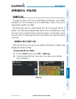
Flight Planning
Hazar
d A
voidance
Additional F
eatur
es
Appendices
Index
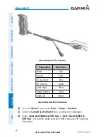
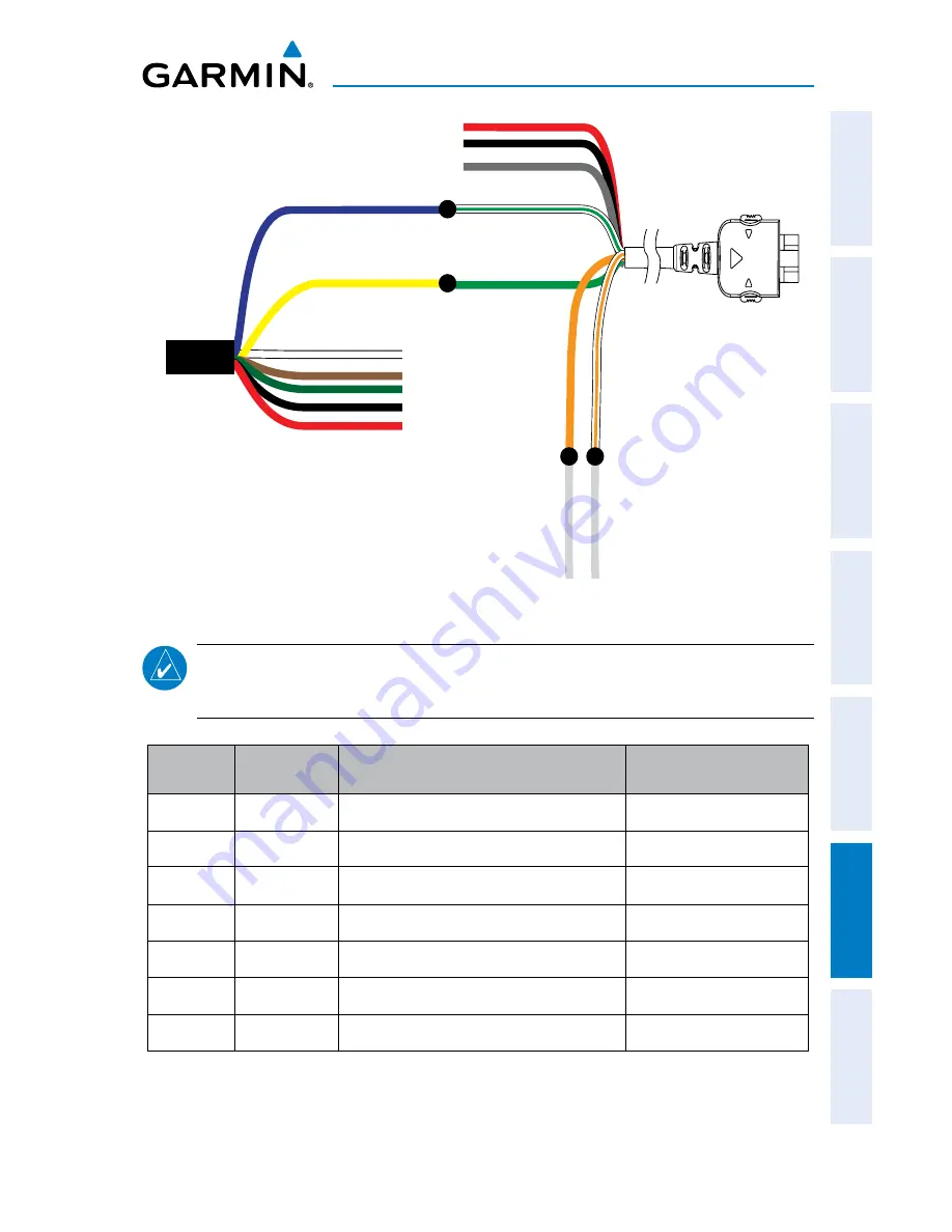
aera Tx
aera Rx
GDL 39 RxA
GDL 39 TxA
GDL 39 TxB
GDL 39 RxB
Additional
Serial
Device Rx
Additional
Serial
Device Tx
aera Bare
Wire Cable
GDL 39 Bare
Wire Cable
Yellow
Yellow
Blue
Blue
White
White
Brown
Brown
Green
Green
Black
Black
Red
Red
White/Green
Green
Green
Gray
Gray
Black
Black
Red
Red
Orange
Orange
White/Orange
White/Orange
(P/N 010-11385-03)
(P/N 010-11686-40)
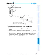
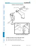
aera/GDL 39 Bare Wire Installation
NOTE:
If the GDL 39 RxB (white/orange wire) is not needed in a serial-pass
through installation, it should be grounded.
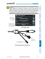
PIN #
Direction
Description
Wire Color
1
IN
Voltage Supply Input
Red
6
GND
Black
10
IN
Serial RxA (GDL39 IN)
White/Green
11
OUT
Serial TxA (GDL39 OUT)
Green
12
IN
Discrete Input
Gray
13
IN
Serial RxB (GDL39 IN)
White/Orange
14
OUT
Serial TxB (GDL39 OUT)
Orange
GDL 39 Bare Wire Cable Pinout (18Pin)
Summary of Contents for aera 560
Page 1: ...models 500 510 550 560 Pilot s Guide...
Page 2: ......
Page 3: ...OVERVIEW GPS NAVIGATION FLIGHT PLANNING HAZARD AVOIDANCE ADDITIONAL FEATURES APPENDICES INDEX...
Page 4: ......
Page 10: ...Garmin aera 500 Series Pilot s Guide 190 01117 02 Rev C Warnings Cautions Notes Blank Page...
Page 12: ...Garmin aera 500 Series Pilot s Guide 190 01117 02 Rev C RR 12 Blank Page...
Page 229: ......