IF630
System Operation/Installation 5/26/01
___________________________________________________________________________________________
Rev 3.0
21
CPU Module (continued)
Installation
Diagram
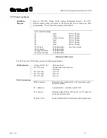
Refer to D-W1145, Wiring, IF630 Analog Addressable System. The CPU
module jumper settings are preset at the factory and do not require any field
programming. Do not place any jumpers on the module.
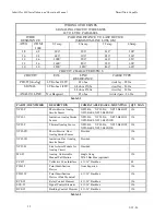
SW1 - Default Settings
S1
Open
Do Not Change
S2
Open
Do Not Change
S3
Always Closed
Do Not Change
S4
Open
Do Not Change
S5
Open
Do Not Change
S6
Open
Do Not Change
S7, S8 Open
9600 Baud Rate
Auto Detect Baud
S7, S8 Closed
4800 Baud Rate
S7 Open, S8 Closed
2400 Baud Rate
S7 Closed, S8 Open
1200 Baud Rate
DIP Switch SW1 Table
The LED’s on the CPU Module provide the following indications:
LED Indication
All four LED's "On"
Hardware Reset
D1 "On" only
Normal Quiescent Condition
Indication
D2 "On" only
not used
D3 "On" only
not used
D4 "On" only
not used
Cable Connections:
IBX1 connector
Interconnection (ribbon cable) to P1 connection on the
bus driver module
P2 connector
Laptop interface - use ribbon cable 71332
P3 connector
Interconnecting cable for CPU power via J13 connector
on the bus driver module
P4 (pins 3 & 4)
System Hardware Reset (momentary short) jumper pins
Summary of Contents for Smart Start IDENTIFLEX 630
Page 2: ......
Page 4: ......
Page 6: ......
Page 11: ...Section 1 IDENTIFLEX 630 System Description...
Page 14: ......
Page 44: ......
Page 117: ...Section 1 IF 600 FIRMWARE VERSION R7 MANUAL SUPPLEMENT Introduction...
Page 123: ...Section 2 IF 600 FIRMWARE VERSION R7 MANUAL SUPPLEMENT Special System Functions...
Page 127: ...Section 3 IF 600 FIRMWARE VERSION R7 MANUAL SUPPLEMENT System Test Mode...
Page 141: ...Section 4 IF 600 FIRMWARE VERSION R7 MANUAL SUPPLEMENT Programming...
Page 201: ...Section 4 IF 600 FIRMWARE VERSION R7 MANUAL SUPPLEMENT Configuration File...


