IF630
System Operation/Installation 5/26/01
___________________________________________________________________________________________
Rev 3.0
9
Alarm Condition
(default)
The IdentiFlex 630 will go into an ALARM
state when any analog/addressable
initiation device reports an alarm condition. By default the following actions will
occur at the common control display. Refer to Table O-1, System Events Messages
for complete listing of message displays.
1.
The red "Alarm" LED will begin flashing. The flash rate is a continuously
repeating sequence of 1/4 second 'On' followed by 1/4 second 'Off'. The
internal system buzzer will sound.
2.
The alphanumeric display will show the identification of the
Alarm
along with
date and time. (Refer to Figure O-2) Alarm information is logged into the
History Buffer to provide a time stamped record of the event's occurrence. In
the event of multiple alarms, the alphanumeric display can be scrolled (using
the up/down arrow keys) to show all active initiating devices.
3.
The red Alarm LED for "City Tie" will light steady to indicate that the city tie
circuit has been activated.
4.
Signaling Circuits indication will be as follows;
The red alarm LED's for (Signal Circuit 1 and Signal Circuit 2) will light
steady to indicate any signaling circuits that have been activated.
5.
The Form C common alarm relay contacts will transfer.
6.
The acknowledge switch red LED will begin to flash. This guided prompt
feature notifies the user that the next expected action is to press the "ACK"
switch - acknowledging the
Alarm Condition
.
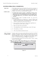
Status : ALARM 1st of 1 MM/DD/YY HH:MM
Fire Alarm in
Ckt#_ Dev#:_
Figure O-2
Display for Multiple Alarm(s)
•
NOTE:
Multiple alarms are shown after the words ALARM Total
“x”; with “x” representing the total amount of alarms.
Status : ALARM Total X MM/DD/YY HH:MM
Fire Alarm in
Ckt#_ Dev#:_
Figure O-3
Summary of Contents for Smart Start IDENTIFLEX 630
Page 2: ......
Page 4: ......
Page 6: ......
Page 11: ...Section 1 IDENTIFLEX 630 System Description...
Page 14: ......
Page 44: ......
Page 117: ...Section 1 IF 600 FIRMWARE VERSION R7 MANUAL SUPPLEMENT Introduction...
Page 123: ...Section 2 IF 600 FIRMWARE VERSION R7 MANUAL SUPPLEMENT Special System Functions...
Page 127: ...Section 3 IF 600 FIRMWARE VERSION R7 MANUAL SUPPLEMENT System Test Mode...
Page 141: ...Section 4 IF 600 FIRMWARE VERSION R7 MANUAL SUPPLEMENT Programming...
Page 201: ...Section 4 IF 600 FIRMWARE VERSION R7 MANUAL SUPPLEMENT Configuration File...

