5. OTHER OPERATIONS
5-10
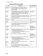
System parameters menu description
Item
Description
Available settings
Ship’s Speed
Average
Set averaging time for ship’s speed. The default
setting is acceptable for most conditions. If the speed
indication is unstable, select the setting that gives
stable speed data.
5s, 10s, 15s, 30s,
60s
Current
Average
Set averaging time for current (tide) speed and direction.
The default setting is acceptable for most conditions. If the
current data changes randomly, select the setting that
gives stable current data, but does not slow response to
changes in current data.
1min, 2min, 3min,
5min, 10min
Track
Depth
Set the water tracking depth for measurement of through-
the-water-speed. If the through-the-water speed readout is
unstable, raise the setting.
0.5 - 25.0(m), 0.1m
steps
Current
Measurement
Set the depth at which to measure current (tide) speed and
direction.
0.5 - 25.0(m), 0.1m
steps
CALC
Average
Smooth the heading data, which is received every second. No Averaging, 10s,
30s, 60s, 90s, 120s
IR
Turn the interference rejector on or off. Turn the rejector on
when an echosounder is connected to the DS-60, to
prevent mutual interference.
ON, OFF
Log Pulse
Speed
Select the data to use to calculate distance run.
STW&GPS;
SOG&STW&GPS;
SOG&GPS; STW
Log Pulse
Output
Select the log pulse speed to output to external equipment.
• Forward: Forward speed only
• Forward-After: Forward and after speeds
• Vector: Synthesized speed consisting of forward, after,
port and starboard speeds
Forward; Forward-
After; Vector
Analog
Speed
Select the source for the analog speed indication.
STW&GPS;
SOG&STW&GPS;
SOG&GPS; STW
Analog
Output
Select the analog speed to output to external equipment.
• Forward: Forward speed only
• Forward-After: Forward and after speeds
• Vector: Synthesized speed consisting of forward, after,
port and starboard speeds
Forward; Forward-
After; Vector
Beam
Direction
Select the beam directions to use to measure speed.
Forward: 0°, 120°, 240°
After: 60°, 180°, 300°
Forward, After
TVG
Curve
Used for internal calculations, and the default setting is
zero. Do not change the setting. Contact a FURUNO agent
or dealer for information.
0 -19
Summary of Contents for DS-60
Page 1: ...DOPPLER SONAR DS 60 OPERATOR S MANUAL www furuno co jp MODEL ...
Page 30: ...2 NAVIGATION DATA DISPLAY 2 10 This page is intentionally left blank ...
Page 44: ...3 BERTHING DISPLAY 3 14 This page is intentionally left blank ...
Page 50: ...4 SPEED GRAPHIC DISPLAY 4 6 This page is intentionally left blank ...
Page 94: ......

