background image

Confidential: FUJIFILM Service Center Use Only


X-Pro1 Service Manual 

3-36 


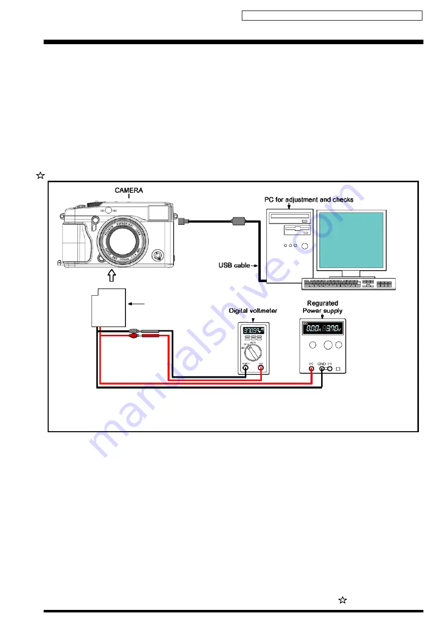
3-17. [F8]: Firmware Download 


[Adjustment environment and precautions] 

• 

Carry out a firmware download when instructed to do so. 

Depending on the firmware that is upgraded, it may be necessary to make adjustments to the camera or to reset the EEPROM.
• 

Do not turn the camera off during firmware downloading. 

Turning the camera off while a download is in progress could damage the camera. (At worst, it may no longer be possible to 
turn the camera on.) 
 

[Required items] 

None 


<Setting for Firmware Download> 


NP-W126 Battery Jig

Revised:13.April.2012

Summary of Contents for X-Pro1

Page 1: ...AD FREE SOLDER WHEN PERFORMING REPAIRS Refer to page 3 WARNING THE COMPONENTS IDENTIFIED WITH THE MARK ON THE SCHEMATIC DIAGRAM AND IN THE PARTS LIST ARE CRITICAL FOR SAFETY PLEASE REPLACE ONLY WITH T...

Page 2: ...heir replacement 4 Look for parts which though functioning show obvious signs of deterioration Point them out to the customer and recommend their replacement 5 Check the B voltage to see it is at the...

Page 3: ...ying out repairs use a designated lead free solder bearing in mind the differing work practices for eutectic solder and lead free solder Differences in the soldering work for lead free and eutectic so...

Page 4: ...Confidential FUJIFILM Service Center Use Only X Pro1 Service Manual 4 MEMO...

Page 5: ...ter Use Only X Pro1 Service Manual 5 CONTENTS 1 Disassembly 1 1 2 Schematics 2 1 3 Adjustments 3 1 4 Inspection 4 1 5 Parts List 1 Packing and Accessories 5 1 6 Parts List 2 Mechanical Block 6 1 7 Ele...

Page 6: ...Confidential FUJIFILM Service Center Use Only X Pro1 Service Manual 6 MEMO...

Page 7: ...l 1 1 1 Disassembly 1 1 Removing the CASE 1 Remove the DECO PLATE LEVER 2 Remove the 1 screw MS2M 1 4X2 0 3 Remove the LEVER FINDER 4 Peel off the GRIP F 5 Peel off the TAPE GRIP F 6 Remove the 4 scre...

Page 8: ...GRIP R LEFT 9 Peel off the SHEET GRIP R RIGHT 10 Peel off the SHEET GRIP F RIGHT 11 Peel off the SHEET GRIP F LEFT 12 Peel off the SHEET FRONT Assembly Assemble by performing the disassembly procedure...

Page 9: ...nter Use Only X Pro1 Service Manual 1 3 1 2 Removing the CONST REAR 1 Remove the 1 screw N MSGM 1 7X2 5 2 Remove the 4 screws N MSGM 1 7 2 5D 3 Remove the 3 screws N MS2M 1 7X3 0 4 Remove the 2 screws...

Page 10: ...Open the CONST REAR in the direction of the arrow 6 Remove the REAR FFC from the MAIN PWB ASSY 7 Peel off the ULTAPE 8 Peel off the CUSHION CN LCD 9 Unlock the connector and remove the LCD FPC Assemb...

Page 11: ...se Only X Pro1 Service Manual 1 5 1 3 Removing the CONST FRAME MAIN 1 Remove the 1 screw MSGM 1 7 2 5 2 Remove the CONST PWB SIDE Double sided tape is applied at point A 3 Remove the CONST PWB SIDE FP...

Page 12: ...Confidential FUJIFILM Service Center Use Only X Pro1 Service Manual 1 6 4 Remove the 4 screws N MSGM 1 7 2 5D 5 Remove the 1 screw N MS2M 1 7 3 0 6 Remove the 2 screws N MSGM 1 7 4 0 4 5 6 6 4 4 4...

Page 13: ...UJIFILM Service Center Use Only X Pro1 Service Manual 1 7 7 Remove the 5 screws MSGM 1 7 2 5 8 Remove the 4 screws BT2M 1 7 3 5 Assembly Assemble by performing the disassembly procedure in reverse 7 8...

Page 14: ...l FUJIFILM Service Center Use Only X Pro1 Service Manual 1 8 1 4 Removing the CONST TOP 1 Unlock the connector and remove the CONST TOP FPC 2 Remove the EYE SENSOR FPC 3 Remove the 1 screws N MSGM 1 7...

Page 15: ...Confidential FUJIFILM Service Center Use Only X Pro1 Service Manual 1 9 4 Remove CONST TOP in the direction of the arrow Assembly Assemble by performing the disassembly procedure in reverse 4...

Page 16: ...ce Center Use Only X Pro1 Service Manual 1 10 1 5 Removing the CONST FPC COMMAND 1 Remove the CONST FPC COMMAND FPC 2 Remove the 2 screws BT2M 1 7 5 0 Assembly Assemble by performing the disassembly p...

Page 17: ...ve the solder in 6 locations 2 Remove the FPC AF 3 Unlock the connector and remove the FINDER DRIVE FPC 4 Remove the FINDER BL FPC 5 Remove the FINDER SHATTER FPC 6 Unlock the connector and remove the...

Page 18: ...Use Only X Pro1 Service Manual 1 12 9 Remove the 2 screws BT2M 1 7 3 5 10 Lift off theY 10241MAINPWB ASSY in the direction of the arrow 11 Remove the EVF FPC Assembly Assemble by performing the disass...

Page 19: ...r Use Only X Pro1 Service Manual 1 13 1 7 Removing the UNIT MOUNT 1 Peel off the ULTAPE 2 Peel off the SHEET INSULATE SINK 3 Peel off the SHEET COND SINK 4 Peel off the SHEET CU SINK 5 Remove the 4 sc...

Page 20: ...Confidential FUJIFILM Service Center Use Only X Pro1 Service Manual 1 14 6 Remove the 1 screw MSGM 1 7 2 5 7 Remove the 2 screws MS2M 1 7 4 0 8 Peel off the SHEET COVER FPS 6 7 8...

Page 21: ...onfidential FUJIFILM Service Center Use Only X Pro1 Service Manual 1 15 9 Remove the SPEKER 10 Remove the 1 screw MSGM 1 7 2 5 Assembly Assemble by performing the disassembly procedure in reverse 9 10...

Page 22: ...ential FUJIFILM Service Center Use Only X Pro1 Service Manual 1 16 1 8 Removing the HOLDER SYNCHRO 1 Peel off the BONDO 2 Remove the solder in 1 location 3 Remove the NUT 4 Remove the PLATE SYNCHRO 1...

Page 23: ...Confidential FUJIFILM Service Center Use Only X Pro1 Service Manual 1 17 5 Remove the SYNCHRO TERMINAL from the HOLDER SYNCHRO Assembly Assemble by performing the disassembly procedure in reverse 5...

Page 24: ...ce Manual 1 18 1 9 Disassembling the UNIT MOUNT 1 Remove the screw MS2M1 7X4 0 2 Remove the 4 screws MS2M1 7X5 0B 3 Remove the FINDER UNIT in the direction of the arrow Notes Be careful not to lose th...

Page 25: ...Center Use Only X Pro1 Service Manual 1 19 4 Remove the 2 screws MS2M1 7X4 0 5 Remove the FINDER BASE in the direction of the arrow 6 Remove 4 solders 7 Peel off the SHEET CU Notes on Assembly SHEET...

Page 26: ...LM Service Center Use Only X Pro1 Service Manual 1 20 8 Remove the 3 screws MS2M1 7X4 0 Tightening torque when assembly 10N cm Tight the screws in the order show in the right picture 9 Remove the CMOS...

Page 27: ...hand so that the same SHIMs will always be set to the same positions during assembly as the original positions 10 Remove the 4 screws BT2M1 7X3 5 11 Remove the GLASS PLATE Notes When disassembling the...

Page 28: ...ro1 Service Manual 1 22 12 Raise the DR GLASS UNIT in the direction of the arrow 13 Peel off the TAPE FPC and remove the DR GLASS UNIT Notes on Assembly TAPE FPC is not reusable Check the bosses to de...

Page 29: ...nly X Pro1 Service Manual 1 23 14 Remove the 3 screws MS2M1 7X4 0 15 Remove the FP SHUTTER Tightening torque when assembly 10N cm 15 Remove 10 solders 16 Remove the screw MS2M1 7X2 0 Tightening torque...

Page 30: ...y X Pro1 Service Manual 1 24 17 Remove the MOUNT FPC 18 Remove the 6 screws MS7M1 7X6 0 19 Remove the MOUNT RING Tightening torque when assembly 18N cm Tight the screws in the order show in the right...

Page 31: ...e Center Use Only X Pro1 Service Manual 1 25 20 Remove the PSP MOUNT Notes on Assembly Be sure to apply the lubricant to the PSP MOUNT Lubricant ZS00185 100 HI LUBE FG 600T 21 Remove the MOUNT LOCK Go...

Page 32: ...y X Pro1 Service Manual 1 26 Notes on Assembly Be sure to apply the lubricant to the MOUNT LOCK Lubricant ZS00135 200 LUBRICANT CFD 409Z 22 Remove the CSP MOUNT LOCK 23 Remove the screw MS2M1 7X3 0N T...

Page 33: ...e Only X Pro1 Service Manual 1 27 24 Remove the HOLDER MOUNT ASSY in the direction of the arrow Precautions when replacing HOLDER MOUNT ASSY MASK_MOUNT is not reusable Assembly Assemble procedure is r...

Page 34: ...l 1 28 1 10 Removing the CONST ASSY FRONT and CONST BATT COVER BATTERY 1 Remove the 3 screws MSAM 1 4 2 5N 2 Remove the SHAFT in the direction of the arrow and then remove the COVER BATTERY Assembly A...

Page 35: ...tial FUJIFILM Service Center Use Only X Pro1 Service Manual 1 29 1 11 Attachment locations 1 Affix the SHEET CU SINK as shown in the figure Top and bottom direction standard Right and left direction s...

Page 36: ...Confidential FUJIFILM Service Center Use Only X Pro1 Service Manual 1 30 2 Affix the SHEET COND SINK as shown in the figure Top and bottom direction standard Right and left direction standard...

Page 37: ...K as shown in the figure 4 Affix the UL_TAPE as shown in the figure 5 Affix the UL_TAPE 30X36mm as shown in the figure UL TAPE ZS00169 100 Top and bottom direction standard Right and left direction st...

Page 38: ...IFILM Service Center Use Only X Pro1 Service Manual 1 32 6 Affix the SHEET CU SINK 2 pieces as shown in the figure 7 Affix the UL_TAPE 19X37mm as shown in the figure UL TAPE ZS00143 100 SHEET CU SINK...

Page 39: ...dential FUJIFILM Service Center Use Only X Pro1 Service Manual 1 33 8 Affix the MASK_MOUNT on the HOLDER MOUNT ASSY as shown in the figure 9 Affix the TAPE FPCs on the MOUNT as shown in the figure Rev...

Page 40: ...fidential FUJIFILM Service Center Use Only X Pro1 Service Manual 1 34 10 Affix the TAPE FPC on the BASE CMOS as shown in the figure 11 Affix the SHEET CU on the CMOUS UNINT as shown in the figure Revi...

Page 41: ...eaned up to remove some dirt and dust please use ethanol with 76 9 to 81 4 vol in density just as the cleaning substrate Ethanol with much higher density more than 81 4 vol is not recommended for clea...

Page 42: ...g standard Top and bottom direction CONST TOP insinuation Right and left direction I make an insinuation at a lateral ups and downs shape Press power More than 20N 3 I press it in spite of all SHEET G...

Page 43: ...red horizontal line side of superior wall 1 and am accompanied 2 I move to the bottom for a thing of push Tool and press it until I put it and 2 red bars region is accompanied 3 In the state that move...

Page 44: ...you comply with curve part 1 of LENS side GRIP and am accompanied and expose it to 3 red lines side and am accompanied 2 I divide the whole red frame moiety into three times and press it Grip press to...

Page 45: ...LEFT laps in Tool 1 A SHEET not having the mixture such as alien substances 2 To the ups and downs side get and there not being advance 3 I press the lateral side Grip press tool Type A ZJ01923 100 3...

Page 46: ...ress tool Type B ZJ01924 100 5 I commute in the arrow direction with a curve part of push Tool and press it 1 I press it until I expose it to 2 red line region in the state that let the curve part of...

Page 47: ...owns shape 1 I perform pasting up from the position becoming the standard of right and left direction and the top and bottom direction 2 I stick the right and left course on the basis of around cross...

Page 48: ...w direction 5 I divide the whole red frame moiety into three times and press it Grip press tool Type B ZJ01924 100 4 I commute in the arrow direction with a curve part of push Tool and press it 1 I pr...

Page 49: ...ction I make an insinuation at a lateral ups and downs shape 1 Perform pasting up from the position becoming the standard of right and left direction and the top and bottom direction 2 I press it in s...

Page 50: ...ip press tool Type A ZJ01923 100 4 I press it with a big mask of push Tool in the arrow direction 1 I press it until I expose it to 2 red horizontal line region in the state that I hinted to the red b...

Page 51: ...d 2 I move to the right side for a thing of push Tool and press it by coming and going until I press it by coming and going until I expose it to 2 red line moiety and am accompanied and expose it to 3...

Page 52: ...Center Use Only X Pro1 Service Manual 1 46 7 Press of press tool in the arrow direction 1 Divide it into 13 times and push it 2 Divide it into four times and push it Grip press tool Type D ZJ01926 10...

Page 53: ...er Screw total torque 0 10 0 02N m 2 I take out TAPE GRIP F and stick it on BASE GRIP F after detachment paper stripping Pasting standard Direction of right and left Chart below standard A part insinu...

Page 54: ...below standard B part insinuation 1 GRIP F to BASE GRIP F runs impossibility all laps department 2 Press GRIP F from the top so that a gap does not occur in GRIP F and BASE GRIP F 4 I take out LEVER...

Page 55: ...inder are necessary Clean environment where garbage is not in if possible Lens which varies in zoom ratio makes a evacuation 1 Lens which varies in zoom ratio makes a evacuation 2 Take off five hooks...

Page 56: ...Confidential FUJIFILM Service Center Use Only X Pro1 Service Manual 1 50 MEMO...

Page 57: ...CTL STREO MIC AM SP AM I2 S DA AD HDMI TypeC CN 19pinI TTX0 TX1 TTX2 TXC I2C Master TMDS Output HDMI_DDSCL HDMI_DDSDA HMDI_INT HPD AU_DA KOI 7 2ch Level SENSER I2C_SCI1 I2C_SDA 1 I2C_SCL 1 PMG_PW_CTL1...

Page 58: ...N _ F I U _ 2 S _ Y E K 9 9 T X E _ G R T _ B R T S 0 1 0 1 B 6 T U O 1 1 1 1 A 6 T U O 2 1 2 1 N _ S C _ T X E _ B R T S 3 1 3 1 N U R V 3 _ 3 4 1 4 1 O D S _ 0 O I S C 5 1 5 1 N _ N O _ G _ D E L 6...

Page 59: ...Confidential FUJIFILM Service Center Use Only X Pro1 Service Manual 2 3 2 3 Mounted Parts Diagrams 2 3 1 MAIN PWBASSY 7...

Page 60: ...Confidential FUJIFILM Service Center Use Only X Pro1 Service Manual 2 4 2 3 2 SHOEFPC 1 F E D C B A 2 3 4 5 6 7 8 9...

Page 61: ...in internal memory Insert an memory card to be used for image backup into the camera and format the card From the SETUP menu reset the frame numbers Select image copying from the playback menu select...

Page 62: ...t use it until there is an instruction 9 End Setting Do the end setting when you end the adjustment software when you set the camera to the Jig mode The firmware is not installed in new Y 10241MAIN PW...

Page 63: ...EDD AAB15C5E04F5 displaylang e n Step 2 After downloading the software complete the installation as directed by the Install wizard 3 2 2 Installing Windows Installer 3 0 Windows 2000 SP4 only Step 1 D...

Page 64: ...stment New jig ZJ01971 100 X Pro1 W PC Soft Ver 1 00 PC adjustment Windows 2000 XP English OS 1 ZJ01970 100 X Pro1 SD BOOT Soft I Main PWB Initialize New jig 1 ZJ01849 100 FxHS20EXR X100 Level chart L...

Page 65: ...t with the color temperature meter adjust the pattern box color temperature to 6100 50K 3 5 Adjustment software installation 3 5 1 Installation of DSC jig driver Since this camera uses the USB for com...

Page 66: ...and the firmware are described to the following The PC adjustment soft decompression and preservation method Step1 The adjustment software is downloaded from WEB and software is installed in the PC We...

Page 67: ...IFILM REPAIR SERVICE X Pro1_W Adjustment Software Uninstall X Pro1_W Adjustment Software Step 2 When the window shown on the right appears click Yes Uninstallation then begins Step 3 When uninstallati...

Page 68: ...be done any software is OK Please prepare each one for the decompression software The decompression and the preservation method of the PC adjustment software and the firmware are described to the foll...

Page 69: ...the C drive on the Adjustment PC Step4 Copy the ffboot bin file and ffsys bin file which are stored in the extracted X Pro1 SD BOOT Soft folder under SD card Copy the LX10RCS bin file which are store...

Page 70: ...der at a distance of around 5 cm 2 Press the switch on the QR code reader The instruction manual is provided in several languages Use the section provided in any language for the setting Refer to the...

Page 71: ...ID input The first time the adjustment software is launched a window appears where you select the repair site ID recorded in the camera during End Setting In this window select the appropriate repair...

Page 72: ...s Storage device Press the X key while the camera is in communication with the PC If you press the X key while the camera is disconnected the Adjustment Software Start up Screen may be slow to reappea...

Page 73: ...t the window shown on the right press the Enter key to proceed Step 3 Repair site ID input The first time the adjustment software is launched a window appears where you select the repair site ID recor...

Page 74: ...e Enter key to proceed X PRO1 Jig Mode Setup Screen 1 Set the Jig mode by using NP W126 Battery jig 7 2V at Battery Voltage Adjustment 2 Set the Jig mode by using DC COUPLER CP W126 AC Adapter 9 0V at...

Page 75: ...ss the X key while the camera is in communication with the PC If you press the X key while the camera is disconnected the Adjustment Software Start up Screen may be slow to reappear and an error may a...

Page 76: ...excluding Firmware Download Because the internal memory is formatted during the MAIN PWB Initialize procedure take particular not to erase customer data when working on repair products Required items...

Page 77: ...cancel the procedure Step 4 Ending MAIN PWB Initialize 1 Turn the camera off 2 Remove the Power cable or jig from the camera 3 Remove USB cable from the camera 4 Press the Enter key Press the Enter ke...

Page 78: ...loppy disk when the CONST ASSY FRONT or Y 10241MAIN PWB ASSY has been replaced The following example assumes the use of the serial No shown at right Step 1 Read the serial number of UNIT MOUNT The num...

Page 79: ...Data Write in the adjustment item select screen Step 7 Preparing the Mount Data Write Mount the camera on a tripod When you have completed the preparations press the Enter key to proceed Take care not...

Page 80: ...e purchase it in a general merchandising store Maker Makita Model SK308PZ When it s following specification equal to SK308PZ the Laser telemeter container is practicable Precision 1mm 10m Line Point l...

Page 81: ...ave completed the preparations press the Enter key to proceed Step 4 1 Set the Level jig in 0 degree When you have completed the preparations press the Enter key to proceed Set up the posture of the c...

Page 82: ...e When you have completed the preparations press the Enter key to proceed Step 7 1 Set the Level jig in 90 degree When you have completed the preparations press the Enter key to proceed Set up the pos...

Page 83: ...key to proceed Step 9 Ending Level Adjustment Normal temperature After completing the adjustments press the Enter key to proceed The adjustment item select screen reappears Set up the posture of the...

Page 84: ...ion method Place the filter LB145 against the pattern box With the filter LB145 in contact with the brightness meter adjust the pattern box brightness to 160 5cd m2 2 Color temperature 6100 50K with L...

Page 85: ...during subsequent adjustment Step 4 Ending CMOS Defect Correction After completing the adjustments press the Enter key to proceed The adjustment item select screen reappears CMOS Defect Correction com...

Page 86: ...9 100 NP W126 Battery jig ZJ01936 100 FUJINON LENS XF35mm F1 4 R Settings for Camera Adjustment Step 1 In the adjustment item select screen select F5 Camera Adjustment Step 2 Preparing the camera adju...

Page 87: ...ents press the Enter key to proceed The adjustment item select screen reappears Camera Adjustment completed Press the Enter key to return to the Adjustment Items Select Screen WB_3200K_NORMAL 1 Set th...

Page 88: ...ZJ01936 100 FUJINON LENS XF18mm F2 R Laser telemeter Marketing product Please purchase it in a general merchandising store Maker Makita Model SK308PZ When it s following specification equal to SK308P...

Page 89: ...parations press the Enter key to proceed Step 4 1 Set the Level jig in 0 degree When you have completed the preparations press the Enter key to proceed Level Adjustment High temperature 1 Prepare a Le...

Page 90: ...ed the preparations press the Enter key to proceed Step 8 Ending Level Adjustment High temperature After completing the adjustments press the Enter key to proceed The adjustment item select screen rea...

Page 91: ...th the adjustment environment a tripod or X Y stage can be used LCD adjustment jig ZJ00585 100 The cable must be connected to a PCI 2747A board installed in a PC LCD JIG COVER ZJ00631 100 attach to th...

Page 92: ...excluded When you have completed the preparations press the Enter key to proceed Step 4 Ending EVF Adjustment After completing the adjustments press the Enter key to proceed The adjustment item selec...

Page 93: ...estart the adjustment software Measure the voltage at the battery jig clip position Ensure that the voltage provided by the regulated power supply does not suddenly decrease during adjustment If the v...

Page 94: ...key to proceed Battery Voltage Adjustment Preparations 1 Check that the NP W126 Battery jig and the camera are connected If not return to the Jig Mode Setup screen and connect the NP W126 Battery jig...

Page 95: ...Ending Battery Voltage Adjustment After completing the adjustments press the Enter key to proceed Battery Voltage Adjustment is completed Press the Enter key to return to the Adjustment Items Select...

Page 96: ...ing on the firmware that is upgraded it may be necessary to make adjustments to the camera or to reset the EEPROM Do not turn the camera off during firmware downloading Turning the camera off while a...

Page 97: ...k into the camera 4 Turn the camera on while holding down the shutter button and up key I 5 Check that the LED is lit green and then press the Enter key Press the Enter key to return to the Adjustment...

Page 98: ...hen the adjustment software is first launched The settings are shown in the table below No setting tasks are included in the End Setting procedure Item Details Repair Date Date information is acquired...

Page 99: ...leted these steps press the Enter key After the OK screen display the Adjustment Software Start up Screen reappears When adjust the same camera again switch camera power off once and please switch cam...

Page 100: ...Confidential FUJIFILM Service Center Use Only X Pro1 Service Manual 3 40 MEMO...

Page 101: ...model numbers items equivalent to KLV 5700 ZJ01936 100 NP W126 Battery jig Common with the adjustment JIG ZJ00525 100 Macro Chart Resolution confirmation ZJ00885 100 LCD INSPECTION DATA For LCD inspec...

Page 102: ...TO SS AUTO 6 DISP BACK 7 Check that the live image and text is displayed 8 Monitor a very bright subject and check that the live image does not dim or darken ZJ01936 100 ZPU0512 100 4 Shock noise chec...

Page 103: ...rs on the LCD monitor 3 Check that movie audio recording ends and that the data is recorded on the SD card 11 Movie audio playback check Playback 1 Set the camera to Playback mode 2 Press the 4 way bu...

Page 104: ...7 EVF dust defect check Playback 1 Change to EVF display 2 Play back a completely white 75 image 3 Play back a completely black image 1 Push the VIEW MODE button 2 Check that there are no noticeable d...

Page 105: ...nter to the inside of a lens mount There is no crease bend dent in a mount pin 24 Shipping inspection Inventory repairs only 1 Mode dial 2 AF changeover switch 3 SETUP frame no 4 Variable power lens 5...

Page 106: ...e Battery and SD card to the camera 3 Turn the camera on 4 Carry out the reset of Camera from MENU 5 Set a camera as follows 1 Shooting mode A Aperture Value 2 ISO 200 3 WB Fluorescent light 3 4 Apert...

Page 107: ...say 20 can distinguish Periphery What the line of the part to say 15 can distinguish STEP 3 Ending Resolution Check If an OK carry out the following 1 Carry out the reset of Camera from MENU 2 Turn t...

Page 108: ...ferent lens at zoom ratio 1 Appearance inspection sample chart is projected on the finder window 2 Finder is turned to a white photographic subject Distance the 20cm see the finder inside 3 Comparativ...

Page 109: ...leaner OLYMPUS HYPER CLEAN EE 3310 or Equivalent goods and ZS00172 100 CLEANING PAPER or Equivalent goods Do not use a blower with a brush Using a blower brush to clean the CMOS could scratch the CMOS...

Page 110: ...ice Center Use Only X Pro1 Service Manual 4 10 Step 5 When the window in the right appears click Install Then installation begins Step 6 When the installation completes and the window in the right app...

Page 111: ...oft Uninstall X Pro1 W Dust Inspection Soft Step 2 When the window in the right appears click Yes Then uninstallation begins Step 3 When the uninstallation completes and the window in the right appear...

Page 112: ...X Pro1 W Dust Inspection Soft X Pro1_W DustInspection Step 3 If this procedure stops at the window in the right press the Enter key to proceed Step 4 1 Connect the camera to the PC using the USB cabl...

Page 113: ...a distance of 24mm or less from the lens face of the camera 2 Adjust the position of the camera so that the camera LCD shows the center of the VIEWER is displayed After completing steps 1 to 2 press t...

Page 114: ...ion SCRIPT LX10 GOMI JPG Step 7 1 Turn the camera off 2 Disconnect the USB cable from the camera Note In a normal environment dusts could stick to the CMOS surface Therefore customers could complain a...

Page 115: ...0 100 LABEL PRODUCT W A107 FBB24527 100 U BOXY 10241 A108 FBB24531 100 TRAYY 10241 A109 FBB24634 100 ACC BOXY 10241 A110 FBB24774 100 HDPE BAG 190 200 A111 FBF08577 100 UNIT BELT RING A112 FBL01619 20...

Page 116: ...PRODUCT E A106 FBB24527 100 U BOX Y 10241 A107 FBB24531 100 TRAY Y 10241 A108 FBB24634 100 ACC BOX Y 10241 A109 FBB24774 100 HDPE BAG 190 200 A110 FBF08577 100 UNIT BELT RING A111 FBL01619 200 LX10 OM...

Page 117: ...U BOX Y 10241 A107 FBB24531 100 TRAY Y 10241 A108 FBB24634 100 ACC BOX Y 10241 A109 FBB24774 100 HDPE BAG 190 200 A110 FBF08577 100 UNIT BELT RING A111 FBL01619 300 LX10 OM FR A112 FBL01619 400 LX10 O...

Page 118: ...FBB24527 100 U BOX Y 10241 A107 FBB24531 100 TRAY Y 10241 A108 FBB24634 100 ACC BOX Y 10241 A109 FBB24774 100 HDPE BAG 190 200 A110 FBF08577 100 UNIT BELT RING A111 FBL01619 200 LX10 OM EN A112 FBU044...

Page 119: ...FBB24527 100 U BOX Y 10241 A107 FBB24531 100 TRAY Y 10241 A108 FBB24634 100 ACC BOX Y 10241 A109 FBB24774 100 HDPE BAG 190 200 A110 FBF08577 100 UNIT BELT RING A111 FBL01619 200 LX10 OM EN A112 FBU044...

Page 120: ...PRODUCT E A106 FBB24527 100 U BOX Y 10241 A107 FBB24531 100 TRAY Y 10241 A108 FBB24634 100 ACC BOX Y 10241 A109 FBB24774 100 HDPE BAG 190 200 A110 FBF08577 100 UNIT BELT RING A111 FBU04414 100 CAMERA...

Page 121: ...7 FBB24527 100 U BOXY 10241 A108 FBB24531 100 TRAYY 10241 A109 FBB24634 100 ACC BOXY 10241 A110 FBB24774 100 HDPE BAG 190 200 A111 FBB24776 100 Russia Warranty A112 FBF08577 100 UNIT BELT RING A113 FB...

Page 122: ...00 TRAYY 10241 A108 FBB24634 100 ACC BOXY 10241 A109 FBB24774 100 HDPE BAG 190 200 A110 FBF08577 100 UNIT BELT RING A111 FBL01619 600 LX10 OMZHS A112 FBU04414 100 CAMERABOXASSY A113 FFZ05432 401 POWER...

Page 123: ...4531 100 TRAY Y 10241 A107 FBB24634 100 ACC BOXY 10241 A108 FBB24773 100 My FUJIFILMpaper A109 FBB24774 100 HDPE BAG 190 200 A110 FBF08577 100 UNIT BELT RING A111 FBL01619 100 LX10 OMJP A112 FBU04414...

Page 124: ...Confidential FUJIFILM Service Center Use Only X Pro1 Service Manual 5 10 MEMO...

Page 125: ...86 100 CUSHION LCD M222 FBB24287 100 SHEET FRONT M223 FBB24303 100 SHEET INSULATE SINK M224 FBB24717 100 SHEET CU SINK M225 FBB24718 100 SHEET COND SINK M226 FBF09457 100 CONST ASSY FRONT M227 FBF0946...

Page 126: ...0 N M S G M 1 7 X 2 5 D M 3 0 7 FB B 2 4 1 1 0 1 0 0 L E V E R FINDE R M 3 0 8 FB B 2 4 1 4 2 1 0 0 B A S E G RIP F M 3 0 9 FB B 2 4 1 4 4 1 0 0 G RIP F M 3 1 0 FB B 2 4 2 4 9 1 0 0 S HE E T G RIP F...

Page 127: ...Parts N o D escripti on Comme n M 401 FBF095 88 1 00 H OLDER MOUN T ASSY M 402 FFZ09378 100 Y 1024 1 MOU NT FPC M 403 FBB2 4173 100 M ASK MOU NT M 404 FFZ09105 100 FP SHU TTER M 405 FBF095 91 1 00 D...

Page 128: ...Confidential FUJIFILM Service Center Use Only X Pro1 Service Manual 6 4 MEMO...

Page 129: ...stspecifiedinthecircuitorthe componentsusedontheset Donotreuseremovedparts Alwaysusenewparts Ref No Parts No Description Comment PWB diagram MAIN PWB ASSY FUSE F501 FFP00039 403 FUSE BATTERY BT151 FFZ...

Page 130: ...Confidential FUJIFILM Service Center Use Only X Pro1 Service Manual 7 2 MEMO...

Page 131: ...4 P3 16 P3 18 P3 20 P3 24 P3 26 P3 28 P3 31 P3 36 P6 1 2012 074 20 Apr 2012 Service manual revision Revised pages P4 1 P4 8 Addition pages P1 37 to P1 38 2012 123 27 Jun 2012 Service manual revision R...

Page 132: ...Confidential FUJIFILM Service Center Use Only X Pro1 Service Manual 8 2...

Reviews: