background image

Operating Manual BKS309.MS


14.08.2018


2


System Description 

2.1


Functional Description Standard Web Guide Controller 

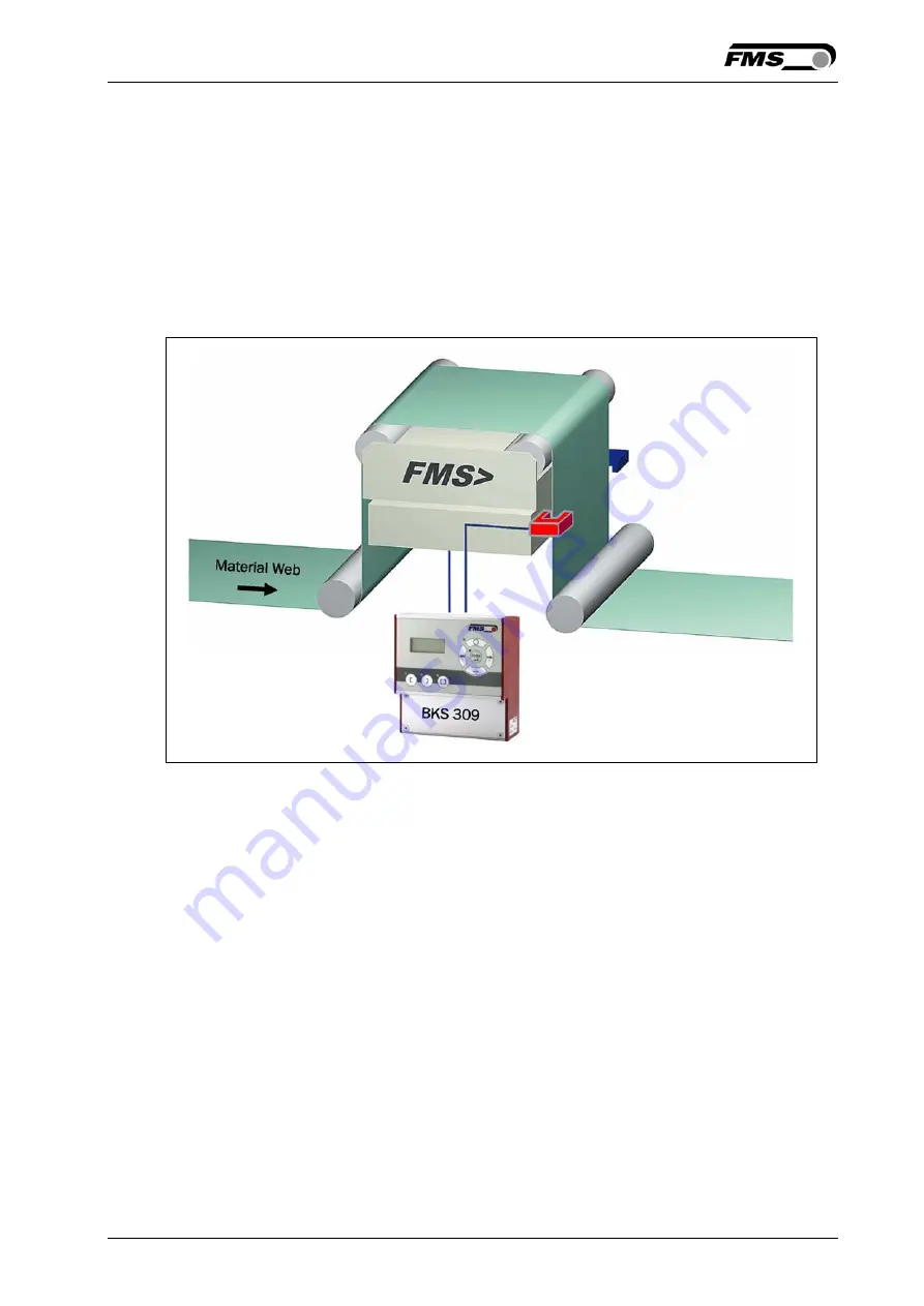
Figure 1 shows a typical web guiding system with its basic components. 
The sensors measure the position of the web edge and send this information as an 
analogue signal to the web guide controller BKS309. This electronics compares the 
position feedback signal with the reference. If the difference of these two values is 
higher then the stored dead band value, the steering frame will be adjusted. 


Fig. 1: Basic system arrangement with BKS309 web guide controller 

K309003e 


2.2


Web Guide Controller with Master-Slave Functionality 

For the lamination of two webs Chase & Follow Control Systems are often used. This 
control system enables the exact positioning of two webs one above the other. The 
BKS309.MS web guide controller with Master-Slave functionality measures the 
position of a first web (Master) and guide a second web (Slave) so that both webs 
exactly match each other. Chase & Follow guiding requires at least one steering 
frame (or actuator) and two material sensors.  
The material sensors are mounted on the same side of the corresponding webs. 
Either both on the left, or both on the right hand side. 
 

Summary of Contents for BKS309.MS

Page 1: ...perating Manual BKS309 MS Digital Web Guide Controller with Master Slave Function Version 2 40 08 2018 NS Firmware Version V2 43 by FMS Force Measuring Systems AG CH 8154 Oberglatt All rights reserved...

Page 2: ...ronic Control Unit 9 5 Wiring Diagrams 10 5 1 Wiring a Steering Frame with BKS309 R S or W Controller 10 5 2 Connecting webMASTERs BKS015 or BKS020 11 5 3 Connecting a winderGLIDE BKS D 3 or a webMAST...

Page 3: ...ters 38 8 7 Reset to Default Parameter Set 40 9 Parameter Setting via a PC 41 9 1 Parameterization in a Network via Web Browser 42 9 2 Parameterization via a PC peer to peer connection 47 10 Mechanica...

Page 4: ...upply before open the housing Proper function of the FMS web guide is only guaranteed with the recommended application of the components In case of other arrangement heavy malfunction can be the resul...

Page 5: ...justed Fig 1 Basic system arrangement with BKS309 web guide controller K309003e 2 2 Web Guide Controller with Master Slave Functionality For the lamination of two webs Chase Follow Control Systems are...

Page 6: ...based drive acts as actuator 2 4 Electronic Control Unit The micro processor based electronic control unit handles all calculations and communications Three buttons and a five key wind rose serve as t...

Page 7: ...frame or actator to the machine 3 Wire the sensors to the electronic unit ref to chapter 5 4 Wire the steering frame to the electronic unit ref to chapters 5 1 to 5 6 5 If using an external web guide...

Page 8: ...4 2 Mounting the Actuator to your Unwind or Rewind Station The static part of the winderGLIDE actuator must be mounted to the machine frame e g to the spherical rod end on the gearbox The moving rod...

Page 9: ...ossed over malfunction can be the result Note For optimum control results the sensors have to be placed next to the exit roller of the steering frame If the sensors are placed far from the steering fr...

Page 10: ...frame or a BKS D 3 D 6 actuator The open ends of the cables must be wired to the cable terminals in the controller according to the wiring diagrams below ref also to Fig 5 or Fig 7 5 1 Wiring a Steeri...

Page 11: ...BKS015 or BKS020 5 3 Connecting a winderGLIDE BKS D 3 or a webMASTER BKS030 The illustration show a BKS D 3 as sample A BKS030 is equally wired 5 4 Connecting a winderGLIDE BKS D 6 Caution Bad earth c...

Page 12: ...Operating Manual BKS309 MS 14 08 2018 12 total system or damage of the control unit It is vital to ensure that the earth connection is properly done...

Page 13: ...sors 3 Switch on your power supply 4 The web guide controller starts up in Manual Operating Mode 5 A web guiding system using BKS309 MS is pre set to control a chase follow application with the master...

Page 14: ...al Name Terminal Relay 1 1 9 Relay 1 2 10 Relay 2 1 11 Relay 2 2 12 6 3 Digital Inputs The BKS309 controller provides 4 digital inputs for special functions The digital inputs are edge or level trigge...

Page 15: ...with the standard web guide controller BKS309 Several functions aren t any more available with the BKS309 MS Parameters connect to these functions are displayed and can be modified without having any...

Page 16: ...ge or on the line if a line sensor is used One sensor is necessary The LED indicates the right edge guiding mode Centre guiding mode is deactivated for BKS309 MS To enter the Parameter Setting Mode ho...

Page 17: ...appen that the web guide controller blocks the steering frame This protective function is activated when the line is interrupted and impossible to detect the line anymore The LED above the key will st...

Page 18: ...on Middle Position and Maximum Positions of the actuator Either you modify the parameters Home Pos Mid Pos and Max Pos in the parameter changing mode or you drive manually to the desired position and...

Page 19: ...To enter the Parameter Setting Mode the web guide controller must be in the Manual Mode In the Automatic Mode only the reference value can be changed Press the key for longer then 3 sec The LED will l...

Page 20: ...Operating Manual BKS309 MS 14 08 2018 20 Fig 13 State Diagram Operation Parameters 1 K309009e...

Page 21: ...Operating Manual BKS309 MS 14 08 2018 21 Fig 14 State Diagram Operation Parameters 2 K309010e...

Page 22: ...Operating Manual BKS309 MS 14 08 2018 22 Fig 15 State Diagram Operation Parameters 3 K309011e_MS...

Page 23: ...Operating Manual BKS309 MS 14 08 2018 23 Fig 16 State Diagram Operation Parameters 4 K309014e_MS...

Page 24: ...the web guide controller must be in the Manual Mode Press the and key together for longer than 3 sec to enter the System Parameter List The LED will light and the first parameter will appear on the LC...

Page 25: ...dSenso MatFound Auto Mat Aut Miss Auto Centre Disabled R1 MidSenso R2 MatFound Digital Input 1 2 3 or 4 Modes Input 1 Input 2 Input 3 Input 4 Edge Aut Lv Auto Centre Ref Ref Centre Lock ResetRef Disab...

Page 26: ...ome Pos mm 0 0 300 0 0 0 3 Middle Position3 Mid Pos mm 0 0 300 0 62 5 5 Maximal Position3 Max Pos mm 0 0 300 0 125 0 5 Actuator Actuator Left Right Left IP Address IP Addr 0 125 192 168 0 090 Subnet S...

Page 27: ...ing Manual Purpose If Manual is chosen the Reference Position is taken from the parameter RefPos Setting Automatic Auto Purpose If Auto behaviour is chosen the Reference Position is determinate by tak...

Page 28: ...edge is at the sensor s middle position Default setting for Relay 1 Setting Material Found MatFound Purpose If MatFound is chosen then the relay goes on when material edge is detected Default setting...

Page 29: ...lled Automatic Mode Lv Auto Purpose The controller switches either to automatic or manual operation depending on the voltage level at the digital input If the voltage is high then the controller switc...

Page 30: ...Move to middle position 1 active irrelevant Stop at actual position Setting Reset of Reference Value ResetRef Purpose This function resets the reference value to 0 if a positive signal edge is applied...

Page 31: ...assword If Password Yes is chosen the system will request the password to change parameters and other setting The password itself can t be changed It is always 3231 The user can choose between two set...

Page 32: ...Purpose The parameter Contrast changes the contrast of the LCD to achieve optimal readability Range 1 to 100 Default 65 Increment 1 Unit Unit System Unit Sys Purpose This parameter determines the uni...

Page 33: ...tic Auto Purpose The controller goes to Automatic Operation Mode after power on Setting Last Setting Used Last Set Purpose The controller restores the operation mode that was previously chosen before...

Page 34: ...ion the sensor input connector for the master web The user can choose between two settings Setting right Purpose The right sensor input is used for the master web default setting Setting left Purpose...

Page 35: ...ctuator Condition This parameter appears on the display only if an actuator winderGLIDE is connected to the controller Maximal Position Max Pos Purpose This parameter determines the limit for the exte...

Page 36: ...actuator is mounted on the right side of the unwind rewind station seen in direction of the running web see Fig 2 IP Addr Purpose The parameter assigns an IP address to the controller This enables th...

Page 37: ...rpose 10 MBPS means 10 M bit per second Factory Settings Default Purpose This menu point is a command It resets the parameters to the factory settings The user can choose between two actions Action No...

Page 38: ...Purpose This parameter adjusts the position of a steering frame exactly to the centre Position Detection PosDetec Purpose This parameter determines what devices that are used to detect the limit posit...

Page 39: ...nly used with the position detection system based on hall sensors For all other position detection system this parameter is not used and hence not displayed The parameter limits the maximum travel to...

Page 40: ...m travel of the spindle will be 200mm 7 87in It is the maximum travel position Type D 3 300 or D 6 300 Purpose If type D 3 300 or D 6 300 is chosen the maximum travel of the spindle will be 300mm 11 8...

Page 41: ...s is not automatically received over DHCP The parameter setting can also be carried out with a desktop or laptop computer via a peer to peer connection see paragraph 9 2 Fig 18 shows the BKS309 config...

Page 42: ...integration of a BKS309 web guide controller in your Ethernet network please contact your IT system administrator Once the BKS309 was integrated in the network you can address the device e g with htt...

Page 43: ...Operating Manual BKS309 MS 14 08 2018 43 Fig 22 Parameter setting and Remote Control Remote Control...

Page 44: ...Operating Manual BKS309 MS 14 08 2018 44 Fig 23 Parameter list webMASTER Steering Frames wMASTER jpg...

Page 45: ...Operating Manual BKS309 MS 14 08 2018 45 Fig 24 Parameter list winderGLIDE Actuators wGLIDE jpg...

Page 46: ...Operating Manual BKS309 MS 14 08 2018 46 Fig 25 Ethernet settings and device addresses Ethernet Settings Fig 26 Firmware update Firware Updates...

Page 47: ...a static IP address If the BKS309 controller is connected to a network by using e g a switch the following procedure is not necessary To establish the connection between your PC and the BKS309 follow...

Page 48: ...nection uses the following items scroll down to Internet Protocol TCP IP Select the Internet Protocol TCP IP and click Properties button The following dialog box will appear Make sure the General tab...

Page 49: ...s for the computer that could be 192 168 0 1 In the Subnet mask enter 255 255 255 000 as shown below Notice that the 000 in both boxes will change automatically to 0 The dialog box will change to look...

Page 50: ...op computer 2 Open Microsoft Internet Explorer or Mizilla Firefox 3 The default IP address for the BKS309 is 192 168 000 090 as long as it was not changed over the operating penal Enter the IP address...

Page 51: ...14 08 2018 51 10 Mechanical Dimensions The BKS309 series is available in three different housing options The mechanical dimensions can be seen in the following pages Fig 27 Outline Drawing BKS309 R r...

Page 52: ...Operating Manual BKS309 MS 14 08 2018 52 Fig 28 Outline Drawing BKS309 W wall mount housing K309008e Fig 29 Outline Drawing BKS309 S panel mount housing K309007e...

Page 53: ...Operating Manual BKS309 MS 14 08 2018 53 Fig 30 Outline Drawing BKS309 R C for DIN real mounting with connectorsK309016e...

Page 54: ...Steering frame does not move No signal sensor not correctly connected Connect sensor correctly according to screw terminal arrangement and installation guide No signal cable interruption Replace cable...

Page 55: ...s Control modes edge left edge right center guiding line guiding Interface Web browser Ethernet Explorer 7 or higher Operation 3 keys and 5 key wind rose pad Analogue inputs 2 inputs 0 10V for sensors...

Page 56: ...technology com www fms technology com FMS USA Inc 2155 Stonington Avenue Suite 119 Hoffman Estates IL 60169 USA Tel 1 847 519 4400 Fax 1 847 519 4401 fmsusa fms technology com FMS UK Aspstrasse 6 8154...

Reviews: