


C1 Controllers and Transmitters
Instruction Manual
September 2009
17
A2202
−
3 / IL
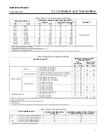
PROPORTIONAL BAND KNOB SETTING
DIFFERENTIAL GAP (PERCENT OF ELEMENT RANGE)
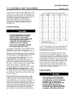
Figure 10. Differential Gap Adjustment for Differential Gap
Controllers
pressure with rising process pressure (direct
−
acting
controllers) or with falling process pressure
(reverse
−
acting controllers).
Adjustment: Proportional Band
The proportional band adjustment shown in figure 4
determines the width of the differential gap. The
width of the gap is the difference between the
process pressures at which the controller output will
switch from zero to full supply pressure, or from full
supply pressure to zero. The relationship between
the proportional band dial setting and the differential
gap is shown in figure 10.
Calibration: Differential Gap Controllers
The output of each controller is checked at the
factory before the unit is shipped. Before placing the
controller in control of a process loop, check to verify
that the controller is calibrated correctly for the
application. The controller must be connected open
loop (Open loop: The controller output pressure
changes must be dead ended into a pressure
gauge).
1. Temporarily convert the differential gap controller
to proportional
−
only controller by disconnecting the
proportional tubing (key 25, figure 16) from the
mounting base. Reinstall the tubing into the other
connection in the mounting base. Remove the
proportional band assembly and invert it as shown in
figure 16. Do not invert the reversing block (key 37,
figure 16).
2. Temporarily invert the proportional band
assembly (refer to figure 18):
a. Turn the proportional band assembly (key 73)
to 10.
b. Unscrew the spring adjustor (key 65),
removing the bias spring (key 70) and washers
(key 62) with it.
c. Unclip the lock spring (key 72). Remove the
indicator scale (key 69) and proportional band
adjustment knob (key 73).
d. Remove the gain adjustment bar (key 63). Flip
it over so it attaches to the opposite side of the
cantilever spring (key 8) as shown in figure 16
and screw it back down.
e. Flip over the indicator scale (key 69); install it
and the proportional band adjustment knob
(key 73) as a unit. Snap in the lock spring
(key 72).
f. Tighten down the spring adjustor (key 65) with
the bias spring (key 70) and washers (key 62)
until it stops against the gain adjustment bar
(key 63).
g. Turn the proportional band adjustment knob to
the 10 setting. If it cannot be turned to the 10
setting, loosen the spring adjustor (key 65).
3. Calibrate using the calibration procedure for
proportional
−
only controllers found on page 10 of
this manual.
4. When calibration is complete, return the tubing
(key 25) and the proportional band assembly to their
original locations and continue on with step 5 of this
procedure.
Note
After reinstalling the tubing (key 25)
and proportional band assembly a
slight offset of the output pressure will
be noticed due to a combination of
switching from the proportional
bellows to the reset bellows and the
repositioning of the cantilever spring.
Performing step 6b below adjusts for
this offset.
5. Refer to figure 10 to determine the proportional
band dial setting required for the desired differential
gap.
For example, assume that a 0 to 100 psig sensing
element is being used and the controller is to switch
from zero to full supply pressure at a process


