


C1 Controllers and Transmitters
Instruction Manual
September 2009
18
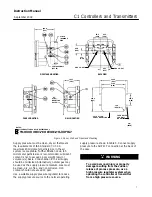
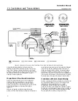
PRESSURE SETTING
DIAL (KEY 6)
ADJUSTER SCREWS (KEY 48)
CALIBRATION ADJUSTER (KEY 36)
FLAPPER (KEY 40)
NOZZLE (KEY 54)
SPAN ADJUSTMENT KNOB
ZERO ADJUSTMENT KNOB
(KEY 58)
GE34729
−
B
E1061
Figure 11. Transmitter Adjustment Locations
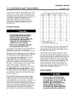
pressure of 80 psig with rising process pressure and
from full supply pressure to zero at 20 psig with
falling pressure. (This is for a direct
−
acting
controller.) The differential gap is:
5.5 bar
*
1.3 bar
6.9 bar
100%
+
60%
80 psig
*
20 psig
100 psig
100%
+
60%
(
)
From figure 10, the proportional band dial setting
should be approximately 4.5; rotate the proportional
band adjustment knob to 4.5.
6. Setting the process pressure
For a Direct
−
Acting Controller:
a. Rotate the pressure setting knob to the
pressure at which the controller output is to
switch to the upper switching point (zero to full
supply pressure) with rising process pressure. In
the above example, this pressure is 5.5 bar (80
psig).
b. Increase pressure to the sensing element
while monitoring the output pressure gauge. The
controller output pressure should switch from
zero to full supply pressure when the upper
switching point is reached with rising input
pressure.
Note
If the upper switching point is not
correct, adjust the nozzle to correct
the error. Repeat step 6b until the
input pressure and upper switching
point are at the desired setting.
c. With falling input pressure, the output should
switch from full supply pressure back to zero
when the lower switching point is reached.
Reverse
−
acting controllers produce the opposite
response.
7. Vary the process pressure and observe the
switching points. Widen or narrow the differential
gap by rotating the proportional band adjustment
knob, then repeat the above steps.
If the output is within the limits stated, refer to the
startup procedures in this section. If the output
pressure cannot be adjusted within the limits stated,
refer to the maintenance procedures.


