


C1 Controllers and Transmitters
Instruction Manual
September 2009
9
line, adequate ventilation, and
necessary safety measures should be
used to prevent the accumulation of
flammable or hazardous gas. However,
a remote vent pipe alone cannot be
relied upon to remove all flammable
and hazardous gas. Vent line piping
should comply with local and regional
codes, and should be be as short as
possible with adequate inside diameter
and few bends to reduce case
pressure buildup.
CAUTION
When installing a remote vent pipe,
take care not to overtighten the pipe in
the vent connection. Excessive torque
will damage the threads in the
connection.
The vent assembly (key 28, figure 2) or the end of a
remote vent pipe must be protected against the
entrance of all foreign matter that could plug the
vent. Use 13 mm (1/2
−
inch) pipe for the remote vent
pipe, if one is required. Check the vent periodically
to be certain it has not become plugged.
Controller Operation
Proportional
−
Only Controllers
This section describes the adjustments and
procedures for calibration and startup. Adjustment
locations are shown in figure 4 unless otherwise
specified. All adjustments must be made with the
cover open. When the adjustments and calibration
procedures are complete, close and latch the cover.
To better understand the adjustments and overall
operation of the controller, refer to the Principle of
Operation section in this manual for
proportional
−
only controllers. Refer also to the
schematic diagram in figure 13.
Adjustments
Adjustment: Set Point
Adjust the pressure setting knob by turning the knob
clockwise to increase the set point and
counterclockwise to decrease the set point. Note
that the dial setting and actual process pressure may
vary significantly, especially with a wide proportional
band setting.
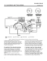
GE33946
−
A
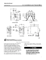
SUPPLY PRESSURE
REGULATOR
SUPPLY PRESSURE
REGULATOR
TYPICAL ROTARY ACTUATOR
TYPICAL SLIDING STEM ACTUATOR
GE33947
−
A
Figure 3. Actuator Mounting
Adjustment: Proportional Band
To adjust the proportional band, rotate the
proportional band adjustment knob to the desired
value.
The proportional band adjustment determines the
amount of change in controlled pressure required to
cause the control valve to stroke fully. It may be
adjusted from 2 to 100 percent for 0.2 to 1.0 bar (3
to 15 psig) or 4 to 100 percent for 0.4 to 2.0 bar (6 to
30 psig) of the nominal sensing element pressure
rating.


