


C1 Controllers and Transmitters
Instruction Manual
September 2009
16
14. Proceed to the Startup procedures for
proportional
−
plus
−
reset controllers.
Calibration: Anti
−
Reset Windup
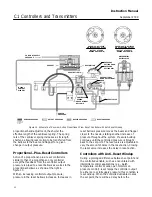
Controllers with anti
−
reset windup have a differential
relief valve assembly (figure 22). This relief valve is
set at the factory to relieve at a 0.3 bar (5 psi)
pressure difference between the reset bellows
pressure and the proportional bellows pressure. The
valve can be adjusted to relieve from 0.14 to 0.4 bar
(2 to 7 psig).
The relief valve can relieve on either rising controller
output pressure or falling controller output pressure.
If the arrow on the relief valve points toward the
bottom of the controller case as shown in figure 22,
the valve will relieve on falling output pressure. If the
arrow points in the opposite direction, the valve will
relieve on rising output pressure. The valve can be
removed and reinstalled with the arrow pointing in
the opposite direction to change the relief action.
Startup: Proportional
−
Plus
−
Reset
Controllers (General Tuning Guidelines)
Calibrate the controller prior to this procedure.
1. Be sure that the supply pressure regulator is
delivering the proper supply pressure to the
controller.
2. Rotate the pressure setting knob to the desired
set point.
3. Start with a reset setting of 0.05 minutes per
repeat (m/r) for fast processes, and 0.5 m/r for slow
processes.
4. Set the proportional band adjustment to 100
percent for fast processes (example: liquid pressure
or liquid flow). For a slow process (example:
temperature), calculate the percentage from the
equation below:
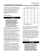
For a slow process, determine the initial proportional
band setting in percent from the following equation:
2
Allowable Overshoot
Pressure Span
100%
+
P.B.
For example:
2
0.14 bar
2.1 bar
100%
^
13%
2
2 psig
30 psig
100%
^
13%
(
)
1.3 proportional band setting
5. Proportional Action:
Disturb the system by tapping the flapper lightly or
change the set point a small amount and check for
system cycling. If the system does not cycle then
lower the proportional band (raising the gain) and
disturb the system again. Continue this procedure
until the system cycles. At that point, double the
proportional band setting and begin tuning the reset.
6. Reset Action:
Disturb the system. If the system does not cycle then
speed up the reset and disturb the system again.
Continue this procedure until the system cycles.
When the system cycles multiply the reset time
setting by a factor of three (3) and slow the reset
down to the new value. The reset is now tuned.
This tuning procedure may be too conservative for
some systems. The recommended proportional band
and reset setting should be checked for stability by
introducing a disturbance and monitoring the
process as previously described. For some
applications, tighter control may be desirable.
Differential Gap Controllers
This section describes the adjustments and
procedures for calibration and startup. The
adjustment locations are shown in figure 4 unless
otherwise specified. The output of each controller is
checked at the factory before the instrument is
shipped.
To convert a differential gap controller to a
proportional
−
only controller or vice versa, refer to the
appropriate procedure in the Maintenance section.
If the process pressure can be varied through all or
part of the sensing element range or through the two
desired switching points, use the process pressure
for calibration. If not, provide a pressure source to
simulate the process pressure range for calibration
procedures.
To better understand the adjustments and overall
operation of the controller, refer to the Principle of
Operation section in this manual for differential gap
controllers and the schematic diagram in figure 13.
Adjustments
Adjustment: Set Point
The position of the pressure setting knob determines
the location of the differential gap within the range of
the pressure sensing element. Move the pointer to
the desired pressure where the output of the
controller should switch from zero to full supply


