


C1 Controllers and Transmitters
Instruction Manual
September 2009
14
Adjustment: Anti
−
Reset Windup
The externally mounted differential relief valve can
be mounted to relieve on increasing or decreasing
output pressure.
Calibration
Calibration: Proportional
−
Plus
−
Reset Controllers
Unless otherwise indicated, key number locations
are shown in figure 7.
Before starting this procedure:
D
Provide a process pressure source capable of
simulating the process pressure range of the
controller.
D
If an output pressure gauge is not provided,
install a suitable pressure gauge for calibration
purposes. The controller must be connected open
loop (Open loop: The controller output pressure
changes must be dead ended into a pressure
gauge).
Note
C1P and C1B controllers with
anti
−
reset windup are supplied with
two O
−
rings (key 81), an anti
−
reset
windup cover (key 80), and two
machine screws (key 82). Use these
parts in the next step.
1. For C1P and C1B controllers with anti
−
reset
windup record the direction of the arrow on the
anti
−
reset windup assembly (key 190, in figure 22).
Remove the assembly and install the two O
−
rings
(key 81), and cover (key 80) supplied with the
controller. Secure the cover with the two machine
screws (key 82) provided.
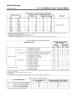
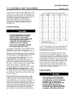
2. Connect regulated supply pressure to the
controller. Do not exceed the normal operating
pressure in table 5.
3. Rotate the reset knob to 0.01 minutes per repeat
(fastest setting).
4. Rotate the proportional band adjustment knob
to 1.5 (15 percent proportional band).
5. Verify that the calibration adjuster screws
(key 48) are at mid
−
position in the calibration
adjuster (key 36) slots.
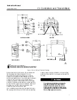
Depending upon the controller action, perform one
or the other of the following procedures.
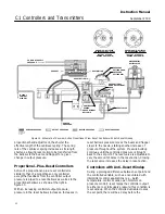
IF OUTPUT IS:
ABOVE
8 TO 10 PSIG
(0.6 TO 0.7 BAR)
BELOW
8 TO 10 PSIG
(0.6 TO 0.7 BAR)
MOVE ADJUSTER
LEFT
MOVE ADJUSTER
RIGHT
FLAPPER
NOZZLE
NOTE:
3 TO 15 PSIG (0.2 TO 1.0 BAR) OUTPUT SHOWN.
FOR 6 TO 30 PSIG (0.4 TO 2.0 BAR) OUTPUT, ADJUST
VALUES AS APPROPRIATE.
A6155
−
1 / IL
Figure 8. Reverse
−
Acting Controller Span Adjustment—
Proportional
−
Plus
−
Reset Controllers
For reverse
−
acting controllers:
6. Apply an input pressure equal to the sensing
element upper range value.
7. Rotate the pressure setting knob to the maximum
value.
8. Adjust the nozzle (key 54) until the controller
output pressure is between 0.6 and 0.7 bar (8
and 10 psig).
9. Apply an input pressure equal to the sensing
element lower range value.
10. Rotate the pressure setting knob to the
minimum value.
Note
When performing the span adjustment
in step 11, do not watch the output
gauge while changing the calibration
adjuster. The change in output is not a
good indication of the change in span.
While moving the calibration adjuster,
the output pressure may change in the
opposite direction than expected. For
example, while moving the calibration
adjuster to increase span, the output
pressure may decrease. This should
be disregarded since even though the
output pressure decreases, the span is
increasing.


