


C1 Controllers and Transmitters
Instruction Manual
September 2009
2
Contents (Continued)
Parts Kits
. . . . . . . . . . . . . . . . . . . . . . . . . . . . . . . .
Parts List
. . . . . . . . . . . . . . . . . . . . . . . . . . . . . . . .
Common Parts
. . . . . . . . . . . . . . . . . . . . . . . . . .
Mounting Parts for Panel, Wall, Pipestand
or Actuator Mounting
. . . . . . . . . . . . . . . . . . .
Introduction
Scope of Manual
This instruction manual provides installation,
operating, maintenance, and parts information for
the Fisher C1 Series pressure controllers and
transmitters shown in figure 1. Refer to separate
instruction manuals for information regarding the
control valve, actuator, and accessories.
Do not install, operate, or maintain C1 Series
pressure controllers and transmitters without first
being fully trained and qualified in valve, actuator,
and accessory installation, operation, and
maintenance. To avoid personal injury and property
damage, it is important to carefully read, understand,
and follow all the contents of this manual, including
all safety cautions and warnings. If you have any
questions about these instructions, contact your
Emerson Process Management sales office before
proceeding.
Description
The C1 Series pneumatic pressure controllers and
transmitters use a bellows or Bourdon tube sensing
element to sense the gauge pressure, vacuum,
compound pressure, or differential pressure of a
liquid or gas. The controller or transmitter output is a
pneumatic pressure signal that can be used to
operate a final control element, indicating device, or
recording device.
Unless otherwise noted, all NACE references are to
NACE MR0175
−
2002.
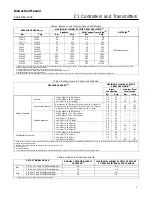
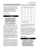
Specifications
Specifications for the C1 Series controllers and
transmitters are listed in table 1. Table 2 explains
available configurations and options.
Educational Services
For information on available courses for C1 Series
controllers and transmitters, as well as a variety of
other products, contact:
Emerson Process Management
Educational Services, Registration
P.O. Box 190; 301 S. 1st Ave.
Marshalltown, IA 50158
−
2823
Phone: 800
−
338
−
8158 or
Phone: 641
−
754
−
3771
FAX: 641
−
754
−
3431
e
−
mail: [email protected]
Installation
WARNING
To avoid personal injury or property
damage resulting from the sudden
release of pressure:
D
Always wear protective clothing,
gloves, and eyewear when performing
any installation operations.
D
Personal injury or property
damage may result from fire or
explosion if natural gas is used as the
supply medium and appropriate
preventive measures are not taken.
Preventive measures may include, but
are not limited to, one or more of the
following; remote venting of the unit,
re
−
evaluating the hazardous area
classification, ensuring adequate
ventilation, and the removal of any
ignition sources. For information on
remote venting of this controller/
transmitter, refer to page 8.
D
If installing into an existing
D
Check with your process or safety
engineer for any additional measures
that must be taken to protect against
process media.
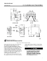
Standard Installation
The instruments are normally mounted vertical with
the case/cover as shown in figure 1. If installing the
instrument in any other position, be sure that the
vent opening shown in figure 2 is facing downward.


