Fisher C1B Instruction Manual Download Page 19

C1 Controllers and Transmitters

Instruction Manual

September 2009

19

Startup: Differential Gap Controllers

Calibrate the controller prior to this procedure.

1.  Be sure that the supply pressure regulator is
delivering the proper supply pressure to the
controller.

2.  Adjust the proportional band setting for the proper
differential gap (see figure 10).

3.  If the controller is used in conjunction with a
control valve, slowly open the upstream and
downstream manual shutoff valves, and close the
bypass valves.

4.  To change the differential gap, perform steps 1
through 5 of the calibration for differential gap
controllers procedure.

Transmitter Operation

This section describes the adjustments and
procedures for calibration and startup. Refer to
figure 11 for the adjustment locations. All
adjustments must be made with the cover open.
When the adjustments and calibration procedures
are complete, close and latch the cover.

To better understand the adjustments and overall
operation of the transmitter, refer to the Principle of
Operation section in this manual for transmitters.
Refer also to the schematic diagram in figure 13.

Adjustments

Adjustment: Zero

The pressure setting dial is marked ZERO
ADJUSTMENT PRESSURE SETTING. Zero is in the
center of the dial, and the pressure values increase
to the right and left of the center as shown in figure
11. To set the zero, rotate the pointer around the
pressure setting dial. Rotate the pointer clockwise to
increase or counterclockwise to decrease the output
depending on transmitter action and desired setting.

For direct

acting transmitters, zero adjustment

determines the process pressure at which the
transmitter output signal will be at its lower range
limit.

The dial (key 6) graduations are approximate
indications of the transmitter zero setting. When
making adjustments, do not rely solely on the dial
setting. Monitor the process pressure and output
pressure to be sure the desired settings are attained.

Adjustment: Span

The span adjustment is graduated from 0 to 10. A
setting of 10 represents a span setting of 100
percent of the process sensing element range. The
transmitter achieves the highest accuracy when the
span is 100 percent.

The transmitter span adjustment shown in figure 11
is the same as the controller proportional band
adjustment.

Calibration: Transmitters

The output of each transmitter is checked at the
factory before the unit is shipped. The transmitter
provides an output signal that is proportional to the
pressure applied to the sensing element. The output
pressure has no direct effect on the process
pressure.

The transmitter is calibrated at the factory and
should not need additional adjustment. Use the
following calibration procedures when the sensing
element has been changed or other maintenance
procedures have altered the calibration of the
transmitter. The following procedures use a 0.2 to
1.0 bar (3 to 15 psig) output pressure range as an
example. For other output pressure ranges [such as
0.4 to 2.0 bar (6 to 30 psig)] adjust the values to
match the application.

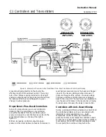
Provide a process pressure source capable of
simulating the process pressure range of the
transmitter. If an output pressure gauge is not
provided, install a suitable pressure gauge for
calibration purposes. Connect a pressure source to
the supply pressure regulator and be sure the
regulator is delivering the correct supply pressure to
the transmitter.

Note

For stability, some transmitter
applications will require additional
volume than just the gauge. Provide a
minimum volume of approximately 25
cm

3

 (1.5 in

3

) or greater if stability is a

problem.

Unless otherwise indicated, key number locations
are shown in figure 11.

1.  Complete the above connections and provide a
process pressure equal to the sensing element
range.

2.  Rotate the span adjustment knob to the
maximum setting on the dial (100 percent span).

Summary of Contents for C1B

Page 1: ...Plus Reset Controllers 16 Differential Gap Controllers 16 Adjustments 16 Adjustment Set Point 16 Adjustment Proportional Band 17 Calibration Differential Gap Controllers 17 Startup Differential Gap Co...

Page 2: ...ications for the C1 Series controllers and transmitters are listed in table 1 Table 2 explains available configurations and options Educational Services For information on available courses for C1 Ser...

Page 3: ...0 4 to 2 0 bar 6 to 30 psig 0 12 normal m3 hour 4 5 scfh Supply and Output Connections 1 4 NPT internal Common Signal Pressure Conversions See table 6 Proportional Band Adjustment For Proportional Onl...

Page 4: ...0 span Hazardous Area Classification Complies with the requirements of ATEX Group II Category 2 Gas and Dust Refer to figure 25 for location of ATEX marking Approximate Weight 8 2 kg 18 pounds Options...

Page 5: ...0 mbar 0 to 10 inch Hg 0 to 1 0 bar 0 to 30 inch Hg 1 4 2 8 2 8 20 40 40 6 9 100 Compound Pressure 75 mbar vac to 75 mbar 30 inch wc vac to 30 inch wc 500 mbar vac to 500 mbar 15 inch Hg vac to 7 5 ps...

Page 6: ...ve actuator mount the instrument according to the following instructions Mounting parts for the different actuator types and sizes vary Two typical actuator mounting installations are shown in figure...

Page 7: ...irements of ISA Standard 7 0 01 A maximum 40 micrometer particle size in the air system is acceptable Further filtration down to 5 micrometer particle size is recommended Lubricant content is not to e...

Page 8: ...r seal systems as needed in the process pressure lines If the instrument is located such that the adjacent process pressure lines will be approximately horizontal the lines should slope downward to th...

Page 9: ...n in figure 4 unless otherwise specified All adjustments must be made with the cover open When the adjustments and calibration procedures are complete close and latch the cover To better understand th...

Page 10: ...s must be dead ended into a pressure gauge The following procedures use a 0 2 to 1 0 bar 3 to 15 psig output pressure range as an example For a 0 4 to 2 0 bar 6 to 30 psig output range adjust the valu...

Page 11: ...g screws key 48 and moving the calibration adjuster key 36 a small distance as indicated in figure 5 10 Repeat steps 4 through 9 until no further adjustment is necessary 11 Proceed to the startup proc...

Page 12: ...example liquid pressure or liquid flow For slow processes example temperature calculate the percentage from the equation below For a slow process determine the initial proportional band setting in pe...

Page 13: ...the indicator points to the desired set point pressure value The pressure setting dial will reflect the desired set point if the controller is accurately calibrated Adjustment Proportional Band To ad...

Page 14: ...es per repeat fastest setting 4 Rotate the proportional band adjustment knob to 1 5 15 percent proportional band 5 Verify that the calibration adjuster screws key 48 are at mid position in the calibra...

Page 15: ...1 do not watch the output gauge while changing the calibration adjuster The change in output is not a good indication of the change in span While moving the calibration adjuster IF OUTPUT IS BELOW 8 T...

Page 16: ...or change the set point a small amount and check for system cycling If the system does not cycle then lower the proportional band raising the gain and disturb the system again Continue this procedure...

Page 17: ...the proportional band assembly refer to figure 18 a Turn the proportional band assembly key 73 to 10 b Unscrew the spring adjustor key 65 removing the bias spring key 70 and washers key 62 with it c...

Page 18: ...ressure with rising process pressure In the above example this pressure is 5 5 bar 80 psig b Increase pressure to the sensing element while monitoring the output pressure gauge The controller output p...

Page 19: ...ly solely on the dial setting Monitor the process pressure and output pressure to be sure the desired settings are attained Adjustment Span The span adjustment is graduated from 0 to 10 A setting of 1...

Page 20: ...adjust the span by loosening the two adjusting screws key 48 and moving the calibration adjuster key 36 a small distance as indicated in figure 12 9 Repeat steps 4 through 8 until no further adjustme...

Page 21: ...e relay diaphragm and loading pressure controller output pressure registers on the small relay diaphragm A change in the process pressure moves the beam and flapper with respect to the nozzle by eithe...

Page 22: ...ontrollers Action of a proportional plus reset controller is similar to that of a proportional only controller except that feedback from the controller output pressure is piped to a reset bellows as w...

Page 23: ...is process continues rapidly until the controller output pressure is at the upper range limit The action of a differential gap controller is so rapid that output pressure changes from zero to maximum...

Page 24: ...stem key 3 must be mounted on the supply pressure regulator CAUTION Before performing this procedure be sure the replacement gauges are the correct range so they are not damaged by overpressure Note K...

Page 25: ...SCREW KEYS 40 AND 46 BELLOWS KEY 52 BELLOWS KEY 52 BELLOWS KEY 52 BELLOWS KEY 52 Figure 15 Reverse Direct Acting Tubing Connections for Proportional Controllers or Transmitter 3 Disconnect the contro...

Page 26: ...acing Bellows Sensing Element Refer to figure 24 for key number locations unless otherwise directed 1 Shut off the supply pressure and process lines to the controller or transmitter 2 Disconnect the t...

Page 27: ...ect the tubing check all connections for leaks and perform the appropriate calibration procedures Changing Anti Reset Windup Differential Relief Valve Refer to figure 23 for key number locations 1 Not...

Page 28: ...sure produces decreasing output pressure to direct action increasing process pressure produces increasing output pressure or vice versa Changing the action is accomplished by reversing the positions o...

Page 29: ...sembly key 37 Inspect the O rings key 77 located in the recessed area under the reversing block screw head and between the reversing block assembly and the calibration adjuster key 36 Replace these O...

Page 30: ...Unscrew the machine screws key 41 figure 21 or 22 and remove the subassembly from the case 4 If the controller or transmitter uses a Bourdon tube sensing element disconnect the Bourdon tube from the...

Page 31: ...art required as found in the following parts list WARNING Use only genuine Fisher replacement parts Components that are not supplied by Emerson Process Management should not under any circumstances be...

Page 32: ...ecified Triple scale Stainless steel 0 2 0 bar 0 0 2 MPa and 0 30 psig 11B8584X022 0 20 bar 0 2 0 MPa and 0 300 psig 11B8584X012 0 69 bar 0 6 9 MPa and 0 1000 psig 11B8584X032 High Temp silicone 1N873...

Page 33: ...0 0 400 0 700 0 700 0 1400 0 1400 0 30 0 30 0 60 0 60 0 100 0 100 0 200 0 200 32B1243X012 32B1243X212 2 32B1243X022 32B1243X172 2 32B1243X032 32B1243X202 2 32B1243X042 32B1243X162 2 0 2000 0 2000 0 40...

Page 34: ...on steel zinc pl 36 Calibration Adjuster 37 Reversing Block 1 Z33520 zinc die casting 38 Sleeve 1 POM polyoxymethylene 39 Beam G10080 carbon steel zinc pl 40 Flapper 1 S30100 SST 41 Machine Screw stee...

Page 35: ...r 71 Gauge Pressure Bellows input 3 Brass 0 150 mbar 0 60 inches wc positive 0 150 mbar 6 60 inches wc vacuum and 75 0 75 mbar 30 0 30 inches wc compound 1L3780000A2 0 250 mbar 0 100 inches wc positiv...

Page 36: ...oportional Band Adjustment Knob steel PPS 74 Machine Screw 1 18 8 SST 2 req d 75 Gasket 1 Std Temp chloroprene 2 req d 1D397003012 High Temp silicone 2 req d 1N873604142 76 Nozzle O Ring 1 Std Temp ni...

Page 37: ...r steel pl for Bourdon tube instruments 2 req d for bellows sensing instruments 4 req d 100 Bellows Yoke zinc use with gauge and differential pressure bellows Note Keys 101 through 105 are used for ga...

Page 38: ...E PRESSURE BELLOWS SENSING ELEMENT SIDE VIEW OF SUBASSEMBLY WITH DIFFERENTIAL PRESSURE BELLOWS SENSING ELEMENT NOTES KEYS 33 46 AND 74 ARE NOT SHOWN KEY 52 IS FEEDBACK BELLOWS KEYS 71K 71L 71M ARE PAR...

Page 39: ...67 For yoke mounting on 480 Vertical For yoke mounting on 1051 and 1052 Size 40 positions 1 and 3 w switch and Size 60 position 1 w switch All others Key Description 213 Mounting Plate steel continued...

Page 40: ...Assembly steel For panel or wall mounting 2 req d 252 Cap Screw steel pl For panel or wall mounting 4 req d Note Specify quantity of fittings Connector Brass 1 4 NPT X 1 4 O D tubing 1 4 NPT X 3 8 O D...

Reviews: