


C1 Controllers and Transmitters
Instruction Manual
September 2009
21
CONSTANT SUPPLY
PRESSURE
EXHAUST
EXHAUST END OF RELAY
BOURDON TUBE
FIXED
PIVOT
BEAM AND
FLAPPER
NOZZLE
VENT
INLET END OF
RELAY VALVE
SMALL DIAPHRAGM
LARGE DIAPHRAGM
TO FINAL
CONTROL
ELEMENT
SENSED
PRESSURE
RESTRICTION
PROPORTIONAL-PLUS-RESET
CONTROLLER
PROPORTIONAL-ONLY
CONTROLLER
GE23696
GE34724
−
A
E1062
PROPORTIONAL
BELLOWS
RESET BELLOWS
SENSED PRESSURE OUTPUT PRESSURE NOZZLE PRESSURE RESET PRESSURE
CANTILEVER
SPRING
RESET
VALVE
RESET
BELLOWS
PRESSURE SETTING DIAL
PRESSURE SETTING KNOB
PROPORTIONAL
BELLOWS
PROPORTIONAL
BAND ADJUSTMENT
KNOB
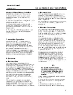
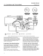
Figure 13. Schematic of Reverse
−
Acting Proportional
−
Only and Proportional
−
Plus
−
Reset Controllers
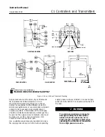
3. If the transmitter is used in conjunction with a
control valve, slowly open the upstream and
downstream manual shutoff valves, and close the
bypass valves.
Principle of Operation
The following sections describe the operation of a
controller or transmitter using a Bourdon tube
sensing element. The operation is the same for an
instrument using a bellows sensing element (key 71,
figure 24) except that movement of the beam is
caused by expansion or contraction of the bellows or
differential bellows.
Proportional
−
Only Controllers
As shown in figure 13, supply pressure enters the
relay and bleeds through the fixed orifice before
escaping through the nozzle. Nozzle pressure also
registers on the large relay diaphragm, and loading
pressure (controller output pressure) registers on the
small relay diaphragm.
A change in the process pressure moves the beam
and flapper with respect to the nozzle by either
expanding or contracting the Bourdon tube arc. An
increasing process pressure with direct action (or
decreasing pressure with reverse action) produces a
nozzle
−
flapper restriction that increases the loading
on the large relay diaphragm and opens the relay
valve. Additional supply pressure flows through the
relay chamber to increase the loading pressure on
the control valve actuator. A decreasing process
pressure with direct action (or increasing pressure
with reverse action) produces a nozzle
−
flapper
opening that bleeds off pressure on the large relay
diaphragm and opens the relay valve to exhaust
controller output pressure from the actuator.
This controller output pressure change feeds back to
the proportional bellows, countering the pressure
change in the nozzle and equalizes the relay
diaphragm pressure differential. The relay valve
maintains a new loading pressure according to the
change in sensed pressure.
If the proportional band adjustment is at its
maximum setting (10), the cantilever spring in the
proportional band assembly has a low spring rate,
allowing more feedback motion to be transferred
from the proportional bellows for a change in output
pressure. As the effective length of the cantilever is
reduced, its spring rate increases, causing less
feedback motion from proportional bellows. Setting
the cantilever spring to its maximum length results in
a proportional band of 100%. The lower the


