


C1 Controllers and Transmitters
Instruction Manual
September 2009
10
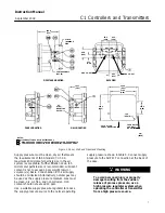
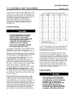
PROPORTIONAL BAND
ADJUSTMENT KNOB
PRESSURE SETTING KNOB
(KEY 58)
PRESSURE SETTING
DIAL (KEY 6)
FLAPPER (KEY 40)
NOZZLE (KEY 54)
CALIBRATION ADJUSTER (KEY 36)
ADJUSTER SCREWS (KEY 48)
GE28280
−
B
E1059
Figure 4. Proportional
−
Only Controller Adjustment Locations
Calibration: Proportional
−
Only
Controllers
Unless otherwise indicated, key number locations
are shown in figure 4.
Provide a process pressure source capable of
simulating the process pressure range of the
controller. If an output pressure gauge is not
provided, install a suitable pressure gauge for
calibration purposes.
Connect a pressure source to the supply pressure
regulator and be sure the regulator is delivering the
correct supply pressure to the controller. The
controller must be connected open loop (Open loop:
The controller output pressure changes must be
dead ended into a pressure gauge). The following
procedures use a 0.2 to 1.0 bar (3 to 15 psig) output
pressure range as an example. For a 0.4 to 2.0 bar
(6 to 30 psig) output range, adjust the values as
appropriate.
1. Complete the above connections and provide a
process pressure equal to the sensing element
range.
2. Rotate the proportional band adjustment knob,
shown in figure 4, to 1.5 (15 percent proportional
band).
3. Verify that the calibration adjuster screws
(key 48) are at mid
−
position in the calibration
adjuster (key 36) slots.
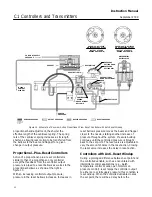
IF OUTPUT IS:
ABOVE
8 TO 10 PSIG
(0.6 TO 0.7 BAR)
BELOW
8 TO 10 PSIG
(0.6 TO 0.7 BAR)
MOVE ADJUSTER
LEFT
MOVE ADJUSTER
RIGHT
FLAPPER
NOZZLE
NOTE:
3 TO 15 PSIG (0.2 TO 1.0 BAR) OUTPUT SHOWN.
FOR 6 TO 30 PSIG (0.4 TO 2.0 BAR) OUTPUT, ADJUST
VALUES AS APPROPRIATE.
A6155
−
1 / IL
Figure 5. Reverse
−
Acting Controller Span Adjustment —
Proportional
−
Only Controllers
Depending upon the controller action, perform one
or the other of the following procedures.
For reverse
−
acting controllers:
4. Apply an input pressure equal to the sensing
element upper range value.


