


C1 Controllers and Transmitters
Instruction Manual
September 2009
7
2 INCH
(NOMINAL)
PIPE
VENT ASSEMBLY
(KEY 28)
FOUR HOLES
FOR WALL
MOUNTING
CUTOUT FOR
PANEL MOUNTING
MOUNTING
HOLES
PANEL MOUNTING
WALL MOUNTING
BACK VIEW
PIPESTAND MOUNTING
mm
(INCH)
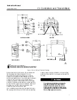
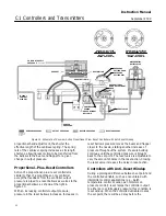
NOTES:
1. ALL CONNECTIONS ARE 1/4 NPT INTERNAL.
HIGH
−
PRESSURE CONNECTION FOR DIFFERENTIAL
−
PRESSURE UNITS.
2
3
LOW
−
PRESSURE CONNECTION FOR DIFFERENTIAL
−
PRESSURE UNITS.
E1052
101.6
(4.00)
14.3
(0.56) R
244.3
(9.62)
215.9
(8.50)
218.9
(8.62)
142.7
(5.62)
69.1
(2.72)
23.1
(0.91)
65.8
(2.59)
63.5
(2.50)
63.5
(2.50)
180.8
(7.12)
8.7
(11/32)
KNOCK
−
OUT
KNOCK
−
OUT
Figure 2. Panel, Wall, and Pipestand Mounting
Supply pressure must be clean, dry air that meets
the requirements of ISA Standard 7.0.01. A
maximum 40 micrometer particle size in the air
system is acceptable. Further filtration down to 5
micrometer particle size is recommended. Lubricant
content is not to exceed 1 ppm weight (w/w) or
volume (v/v) basis. Condensation in the air supply
should be minimized. Alternatively, natural gas may
be used as the supply pressure medium. Gas must
be clean, dry, oil
−
free, and noncorrosive. H
2
S
content should not exceed 20 ppm.
Use a suitable supply pressure regulator to reduce
the supply pressure source to the normal operating
supply pressure shown in table 5. Connect supply
pressure to the SUPPLY connection at the back of
the case.
WARNING
To avoid personal injury or property
damage resulting from the sudden
release of process pressure, use a
high pressure regulator system when
operating the controller or transmitter
from a high pressure source.


