


C1 Controllers and Transmitters
Instruction Manual
September 2009
23
controller output responds to the change in
controlled variable. Anti
−
reset windup minimizes this
delay and permits returning the controlled variable to
set point more quickly with minimal overshoot.
As shown in
figure 14 a proportional
−
plus
−
reset
controller with anti
−
reset windup includes a
differential relief valve. The valve consists of two
pressure chambers separated by a spring
−
loaded
diaphragm.
For the controller shown in figure 14, proportional
pressure registers rapidly on the spring side of the
relief valve diaphragm as well as in the proportional
bellows, and reset pressure registers on the
opposite side of the relief valve diaphragm. As long
as controlled pressure changes are slow enough for
normal proportional and reset action, the relief valve
spring will keep the relief valve diaphragm from
opening. However, a large or rapid decrease in
controller pressure will cause the relay to exhaust
loading pressure from the control device rapidly, and
also from the proportional system and spring side of
the relief diaphragm. If this decrease on the spring
side of the diaphragm is greater than the relief valve
spring setting, the diaphragm will move off the relief
valve orifice and permit the proportional pressure on
the opposite side of the relief valve diaphragm to
bleed rapidly into the reset bellows. The anti
−
reset
windup action also can be reversed to relieve with
an increasing proportional pressure.
Differential Gap Controllers
With a differential gap controller, feedback pressure
does not counteract the change in flapper position
as it does in a proportional
−
only controller. Instead,
feedback pressure is piped to the bellows located on
the side of the beam and flapper opposite the nozzle
(the proportional bellows in figure 13). Then, as
controller output pressure increases, feedback
pressure moves the flapper closer to the nozzle to
again increase controller output pressure. This
process continues rapidly until the controller output
pressure is at the upper range limit. The action of a
differential gap controller is so rapid that output
pressure changes from zero to maximum as soon as
the switching point is reached. The action is similar
with falling output pressure. Lower feedback
pressure lowers the bellows pressure, which moves
the flapper away from the nozzle. This again
reduces the output pressure and continues until the
output pressure is zero.
Transmitters
Action of a pneumatic transmitter is similar to that of
a proportional
−
only controller. Since the output
pressure of the transmitter has no effect on the
process pressure, transmitter output pressure is a
proportional measure of the process pressure. The
proportional band adjustment determines the span of
the transmitter, and the pressure setting mechanism
determines the zero of the transmitter.
Maintenance
If the installation includes a Fisher 67 Series filter
regulator, periodically open the drain on the filter
regulator to drain accumulated moisture. Also, push
the spring
−
out cleaning wire on the relay orifice.
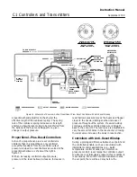
Check the opening of the vent assembly (key 28,
figure 2) or the opening of the remote vent pipe, if
one is used. If necessary, clean the openings.
Parts are subject to normal wear and must be
inspected and replaced as necessary. The
frequency of inspection and parts replacement
depends upon the severity of the service conditions.
WARNING
The following maintenance procedures
require taking the controller out of
service. To avoid personal injury and
property damage caused by the
release of pressure or process fluid,
observe the following before starting
maintenance:
D
Always wear protective clothing,
gloves, and eyewear.
D
Provide some temporary means
of control for the process before
taking the controller out of service.
D
Provide a means of containing the
process fluid before removing any
measurement devices from the
process.
D
Use lock
−
out procedures to be
sure that the above measures stay in
effect while you work on the
equipment.
D
Personal injury or property
damage may result from fire or
explosion if natural gas is used as the
supply medium and appropriate


