


C1 Controllers and Transmitters
Instruction Manual
September 2009
35
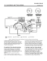
NOTE:
KEYS 11, 21, 22, 29 ARE NOT SHOWN
GE28281
−
B
E1071
RELAY ASSEMBLY
SUBASSEMBLY (KEY NOS.
SHOWN IN FIGURE 23 OR 24)
PROPORTIONAL-PLUS-RESET CONTROLLER
WITHOUT ANTI-RESET WINDUP
SPRING
−
OUT CLEANING WIRE
Figure 22. Typical Reverse Acting Fisher C1 Proportional
−
Plus
−
Reset Assembly
(Refer to figure 25 for the Front View of the Case & Cover Assembly)
Key
Description
Part Number
58
Knob, PPS (polyphenylene sulfide)
59
Knob Spring, steel/zinc pl
60
Washer, G10100 carbon steel, zinc pl
61
Machine Screw, steel pl
62
Washer
, brass/zinc pl (2 req’d)
63
Gain Adj Bar, A03600
64
Washer, 18
−
8 SST (2 req’d)
65
Spring Adjustor, 18
−
8 SST
66
Travel Stop Assembly, SST
Use w/optional Bourdon tube travel stop
67*
Inner Flexure, S30200
GE26663X012
68*
Outer Flexure, S30200
GE26664X012
69
Indicator Scale, aluminum
70
Bias Spring, S30200
Key
Description
Part Number
71*
Gauge Pressure Bellows (input)
Brass
0
−
150 mbar (0
−
60 inches wc) positive, 0
−
150 mbar
(6
−
60 inches wc) vacuum, and 75
−
0
−
75 mbar
(30
−
0
−
30 inches wc) compound
1L3780000A2
0
−
250 mbar (0
−
100 inches wc) positive
1L3788000A2
0
−
0.35 mbar (0
−
5 psig) positive and for
0
−
350 mbar (0
−
10 inches Hg) vacuum
1L3781000A2
0
−
0.5 bar (0
−
7.5 psig) positive
1L3789000A2
0
−
0.7 bar (0
−
10 psig) positive
1L3782000A2
0
−
1.0 bar (0
−
15 psig) positive, 0
−
1.0 bar
(0
−
30 inches Hg) vacuum, and 500
−
0
−
500 mbar
(15
−
0
−
7.5 psig) compound
1L3783000A2
0
−
1.4 bar (0
−
20 psig) positive
1L3784000A2
0
−
2.0 bar (0
−
30 psig) positive and 1.0
−
0
−
1.0 bar
(30
−
0
−
15 psig) compound
1L3785000A2
Stainless steel,
0
−
1.0 bar (0
−
15 psig) positive, 0
−
1.0 bar
(0
−
30 inches Hg) vacuum, and 500
−
0
−
500 mbar
(15
−
0
−
7.5 psig) compound
1L3786000A2
0
−
2.0 bar (0
−
30 psig) positive, 1.0
−
0
−
1.0 bar
(30
−
0
−
15 psig) compound
1L3787000A2
*Recommended spare parts
1. This part is included in the Controller Repair Kit.
3. If ordering the bellows (key 71) to change the range of a gauge pressure
controller, also order the appropriate bellows spring (key 80). Also order
keys 101, 102, and 103 if you do not have them.


