


C1 Controllers and Transmitters
Instruction Manual
September 2009
28
PROPORTIONAL BAND ADJUSTMENT KNOB
(KEY 73)
LOCK SPRING
(KEY 72)
CANTILEVER SPRING
(KEY 8)
BIAS SPRING
(KEY 70)
WASHER
(KEY 64)
SPRING ADJUSTOR
(KEY 65)
MACHINE SCREW
(KEY 56)
INDICATOR SCALE
(KEY 69)
MACHINE SCREW
(KEY 74)
GAIN ADJUSTMENT BAR
(KEY 63)
GE34725
−
A
E1067
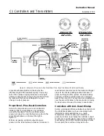
Figure 18. Proportional Band Assembly
c. Unclip the lock spring (key 72). Remove the
indicator scale (key 69) and proportional band
adjustment knob (key 73).
d. Remove the gain adjustment bar (key 63). Flip
it over so it attaches to the opposite side of the
cantilever spring (key 8), as shown in figure 16,
and screw it back down.
e. Flip over the indicator scale (key 69); install it
and the proportional band adjustment knob
(key 73) as a unit. Snap in the lock spring
(key 72).
f. Tighten down the spring adjustor (key 65) with
the bias spring (key 70) and washers (key 64)
until it stops against the gain adjustment bar
(key 63).
g. Turn the proportional band adjustment knob to
the 10 setting. If it cannot be turned to the 10
setting loosen the spring adjustor (key 63).
5. Check all connections for leaks with a
soap
−
and
−
water solution. Perform the appropriate
calibration procedure.
Reverse to Direct Action
Use the numbered steps below to change from
reverse action (increasing process pressure
produces decreasing output pressure) to direct
action (increasing process pressure produces
increasing output pressure), or vice versa. Changing
the action is accomplished by reversing the positions
of the reversing block, proportional band assembly,
and bellows tubing(s). Refer to figures 15, 16, 18,
and 19 for key number locations unless otherwise
directed.
1. Isolate the controller or transmitter from process,
control, and supply pressure. Vent any trapped
pressure from the controller or transmitter before
proceeding with this procedure.
2. As shown in figure 15, locate the new tubing,
proportional band assembly, and reversing block
positions for the desired action.
3. Locate the two bellows (key 52), the proportional
band assembly (see figure 15), and the reversing
block (key 37).
4. Disconnect the tubing (refer to figure 15):
a. For a proportional
−
only controller or for a
transmitter, disconnect the proportional tubing
(key 25) from the mounting base and reconnect
them on the opposite side.
b. For a proportional
−
plus
−
reset controller,
disconnect the proportional tubing (key 27) and
reset tubing (key 27) from the mounting base and
reconnect them on the opposite side.
5. Invert the proportional band assembly (refer to
figure 18):
a. Turn the proportional band adjustment knob
(key 73) to 10.
b. Unscrew the spring adjustor (key 65),
removing the bias spring (key 70) and washers
(key 64) with it.
c. Unclip the lock spring (key 72). Remove the
indicator scale (key 69) and proportional band
adjustment knob (key 73).


