2
Product description for safety module CAMC-G-S1
Festo – GDCP-CAMC-G-S1-EN – 1412b – English
21
2.4.2
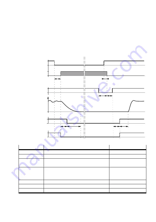
Time behaviour for activating STO during operation with restart
Fig. 2.4 displays the time behaviour starting from interruption of the control voltage to STO-A/B ,as well
as the sequence required to allow the device to restart. The time specifications can be found in
–
The holding brake is activated via the motor controller, not a safety function.
–
The coasting of the motor, irrespective of brake activation/deactivation, is displayed.
–
The setpoint value is only activated when the holding brake delay T_BRAKE_V has expired.
STO-A / STO-B
Status LED
(~ C1/C2)
CAMC-G-S1
1
0
on
off
CMMP-AS-…-M3
Holding brake
(optional)
1
0
T_STO-A/B_OFF
T_DIN5_LOW
STO – “Safe Torque Off ” active
T_STO-A/B_ON
T_DRIVE_V
Speed
Controller enable
DIN5
24 V
0 V
1
0
“Output stage
enable” (internal)
T_DIN5_SU
T_BRAKE_V_OFF
T_DRIVE_V
T_BRAKE_V_ON
Fig. 2.4
Time behaviour when activating the safety function STO with restart
Time
Description
Value
T_STO-A/B_OFF
STO-A/B – Switching time from High to Low
è
T_STO-A/B_ON
STO-A/B – Switching time from Low to High
è
T_DIN5_LOW
Time for which the DIN5 must be Low before
STO-A/B is switched on again
0 ms
T_DIN5_SU
Time for which the DIN5 must be Low after
switching on STO-A/B again and status change
ofthe STO module
20 ms
T_DRIVE_V
Delay of the CMMP-AS-M3
0 … 10 ms
T_BRAKE_V_ON
Switch off delay of the holding brake
T_BRAKE_V_OFF
Switch on delay of the holding brake
1)
Physical delay until the brake closes.
2)
Minimum time: Physical delay until the brake opens. This time can be parameterised in the controller via a large value.
Tab. 2.6


