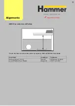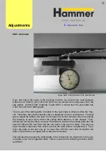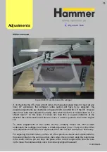
Figure SS01.2 End position of the dial indicator
If we had zero’d the scale in the previous position, we should now read between
0.90mm and 0.95mm (not 0.05mm-0.10mm as we should be moving away from the
saw blade). (0.096”-0.098” Imperial). Figure SS01.2 shows that the saw blade has
0.004” toe-out to the sliding table.
The toe-out of the sliding table in relation to the saw blade is what provides the ‘free-
cut’. Therefore, the position that the table is tightened down in controls this. The best
way to adjust the table to this level of accuracy is to loosen all lower-most nuts (inside
the chassis) at each point where the sliding table attaches to the chassis. Then,
without yet moving the table, measure the distance between the sliding table and the
cast iron table at the very front and the very back of the cast iron table. This way you
have created a reference from which to move the table before re-tightening it. Try to
move the table at one end only by no more than 0.25mm each time. Re-tighten the
table, check the free-cut again and re-adjut as necessary
This will also then require the sliding table to be checked for it’s alignment to the cast
iron table, once it is re-tighened down. This is covered in the following sections, SS02
and SS03.
Adjust
ments
SS01
continued
Summary of Contents for Hammer
Page 1: ...Machine Setup Guide InstallVersion1 09...
Page 5: ...15 Completion You re Good To Go 16 FAQ s 17 Links Contact Details Contents 3...
Page 32: ...The rip fence side is complete 11 Assembly...
Page 74: ...Figure SS03 2 End position 2 Adjustments Alignme nt Link SS03 continued...
Page 79: ...Figure SS07 3 Crosscut stop and block adjustment Adjustments Alignme nt Link SS07 continued...

