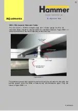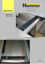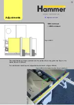
You will need a 1000mm straight edge and a feeler gauge for this. All
extension tables should be aligned within the specified tolerance. Figure SR01.1.1
show the functions of the main supporting screws and nuts.
Figure SR01.1.1
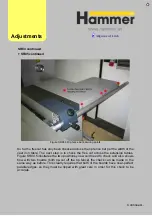
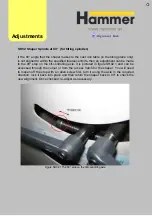
The additionsl screws that support the table obviously do not attach to the table, but
provide support under the table to take-up any out-of-tolerance gaps. They are
shown in figure SR01.1.2.
Adjust
ments
Continued…
S
R01.1 Rip Capacity Extension Tables
Summary of Contents for Hammer
Page 1: ...Machine Setup Guide InstallVersion1 09...
Page 5: ...15 Completion You re Good To Go 16 FAQ s 17 Links Contact Details Contents 3...
Page 32: ...The rip fence side is complete 11 Assembly...
Page 74: ...Figure SS03 2 End position 2 Adjustments Alignme nt Link SS03 continued...
Page 79: ...Figure SS07 3 Crosscut stop and block adjustment Adjustments Alignme nt Link SS07 continued...


