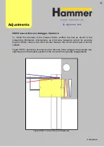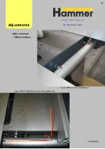
Once the sliding table has been adjusted in the centre locked position, we can look at
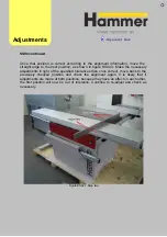
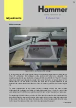
the table in its end positions. The best way to do this is by putting the sliding table
and the straight edge in the position shown in figure SS03.1. Check the alignment
here and make any adjustment using the centre fixing points also shown in the
picture.
Figure SS03.1 End position 1
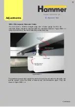
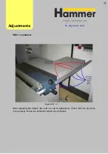
When making any adjustments, always check the table at both ends. The other
position is shown in figure SS03.2. Because the two end postions are adjusted at the
same position, if it is not possible to adjust both ends to within tolerance, it is due to a
mis-alignment in the centre locked position. Even if the centre locked position
indicated that both sides were within tolerance, if one side was at the lower limit of
the tolerance and the other at the higher limit, it would cause the sliding table to
move out of tolerance.
Adjust
ments
Continued…
SS0
3 Sliding Table End Positions
Summary of Contents for Hammer
Page 1: ...Machine Setup Guide InstallVersion1 09...
Page 5: ...15 Completion You re Good To Go 16 FAQ s 17 Links Contact Details Contents 3...
Page 32: ...The rip fence side is complete 11 Assembly...
Page 74: ...Figure SS03 2 End position 2 Adjustments Alignme nt Link SS03 continued...
Page 79: ...Figure SS07 3 Crosscut stop and block adjustment Adjustments Alignme nt Link SS07 continued...


