background image


1


1-800-543-545

4


(

801) 927-3026


IDEAL CUTTERS 

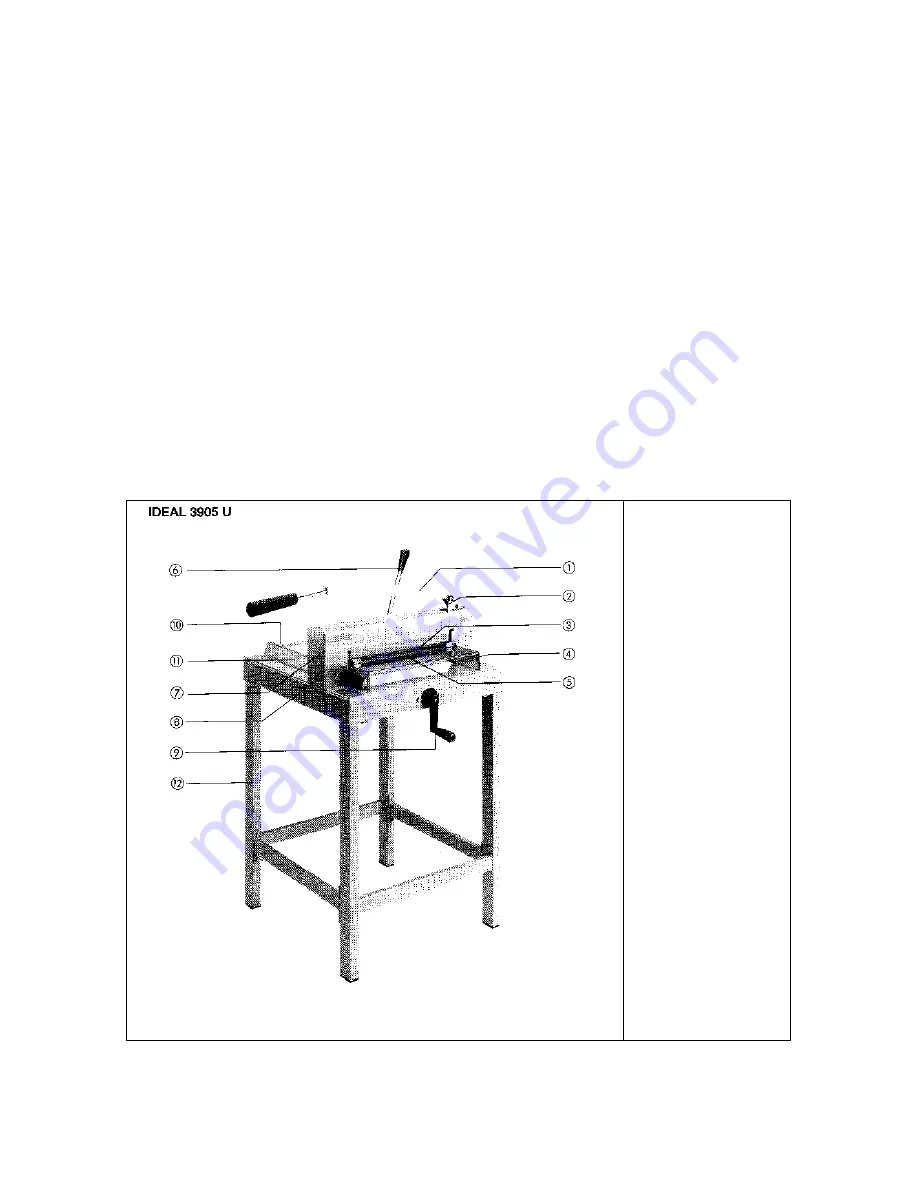
Model 3905 

Model 3905 U 


1.  Knife lever 
2.  Knife lock 
3.  Knife 
4.  Cutting stick 
5.  Hand guard 
6.  Clamping lever 
7.  Cover 
8.  Knife 

adjustment 

9.  Back gauge 

crank with fine 
measuring 
adjustment 

10.  Back gauge 
11.  Side gauge 

with scale 

12.  Stand 

Office Zone

1-800-543-5454

Summary of Contents for IDEAL 3905

Page 1: ... 3905 Model 3905 U 1 Knife lever 2 Knife lock 3 Knife 4 Cutting stick 5 Hand guard 6 Clamping lever 7 Cover 8 Knife adjustment 9 Back gauge crank with fine measuring adjustment 10 Back gauge 11 Side gauge with scale 12 Stand Office Zone 1 800 543 5454 ...

Page 2: ...ediately IDEAL 3905 U Top part and stand of the machine have to connected as follows Set up the stand in a way that the 4 threaded pins point upwards On each threaded pin there is a washer and a hexagonal nut which has to be removed Place the cutter correctly onto the machine stand Fit the washers and tighten the hexagonal nut with wrench size 13 Performance You can cut many varieties of paper and...

Page 3: ...ndle lever to the right Flick action clamping system open Hand lever to the left Flick action clamping system closed ready to cut 7 Cover Attached to the machine with two screws Disassemble only in case of knife change or maintenance 8 Knife adjustment The knife can be adjusted without the knife being loosened by using the adjustment screw 8 Turn to the left Knife adjustment downwards Turn to the ...

Page 4: ...ainst the back gauge 10 and along the side gauge 11 on the left Push the back gauge crank 9 toward the cutter to engage and then turn the crank handle 10 clockwise to bring the back gauge toward the knife until the paper measurement is reached With the help of the fine adjustment ring accurate measurement can easily be reached Release the back gauge crank 9 so that the unintentional movement of th...

Page 5: ...nt of the machine as follows a The knife lever 1 is locked in the top position b Remove the 2 screws in the cover 7 Unlock knife level 1 and turn it slightly to the left Then take off the cover 7 c Return the knife lever 1 to its starting position and lock it d Open the hand guard 5 to the top e Remove knife screws B and D and replace them with the two knife holders from the tool box Tighten secur...

Page 6: ... down via the knife lever 1 once more Tighten knife screws A E p Assemble the cover 7 q Important The clamp bar must be adjusted in a way that the cutting edge of the knife in its home position is covered by the clamp bar ...

Reviews: