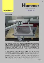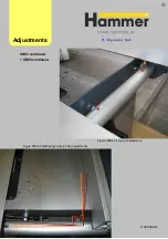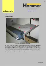
Figure SS08.3 From the back of the outrigger
If, on checking the 45° angle at both sides, the measured angle does not read (at any
time) 45° accurately, the outrigger centre section will have to be adjusted. The
possible adjustments are illustrated in figures SS08.4 and SS08.5. If the 90° crosscut
stops have both been adjusted correctly, then when the fence is locked down at 0° it
should read 0° on the scale. If it does not, then this is a good indication of the
direction the centre section will have to move in order to produce the correct angled
cut.
To make adjustments to the centre section, carefully loosen the allen screws
underneath the outrigger and make a small adjustment (max. 1mm) at a time. After
each adjustment check the new alignment with a test cut and re-adjust as necessary.
For adjusting the miter index, perform all of the previous checks and adjustments for
the scale printed on the centre section, then when this is correct, align the miter index
to the scale until the pin can drop into place at the correct angles each time. Be sure
not to move the centre section once it is correctly aligned however!
Adjust
ments
Continued…
SS0
8 continued
Summary of Contents for Hammer
Page 1: ...Machine Setup Guide InstallVersion1 09...
Page 5: ...15 Completion You re Good To Go 16 FAQ s 17 Links Contact Details Contents 3...
Page 32: ...The rip fence side is complete 11 Assembly...
Page 74: ...Figure SS03 2 End position 2 Adjustments Alignme nt Link SS03 continued...
Page 79: ...Figure SS07 3 Crosscut stop and block adjustment Adjustments Alignme nt Link SS07 continued...


