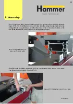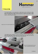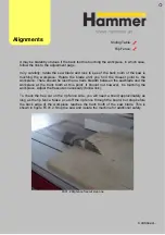
When you are happy that the sliding table is in the correct position, lock it down by
tightening the top nut on each screw only, leaving the two on either side of the
chassis alone (otherwise you will alter the alignment of the sliding table to the cast
iron table). This screw is shown in figure ST01.6
Figure ST01.6 Showing the three locking nuts. ONLY
After the sliding table locke down, you can assemble the end plate(s) to the bed of
the slding table, shown in figure ST01.7
ST01.7 Coverplates for sliding table bed
use the top one to lock the slding table in place!
11.Assembly
Summary of Contents for Hammer
Page 1: ...Machine Setup Guide InstallVersion1 09...
Page 5: ...15 Completion You re Good To Go 16 FAQ s 17 Links Contact Details Contents 3...
Page 32: ...The rip fence side is complete 11 Assembly...
Page 74: ...Figure SS03 2 End position 2 Adjustments Alignme nt Link SS03 continued...
Page 79: ...Figure SS07 3 Crosscut stop and block adjustment Adjustments Alignme nt Link SS07 continued...


