background image

55

HNC3 825 / HNC3 825 perform

Maintenance

Personnel:

Trained machine operator

Protective equipment:

Protective clothing

Protective gloves

Protective footwear

Safety goggles

Tool:

Grease gun

Cleaning cloths

Hex key

Material:

Lubricant Interflon Grease HD2

Interval: Twice a year or if noises occur.

1.

Position the working head on the right.

2.

Switch off the machine at the main switch, disconnect the power supply.

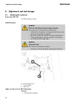
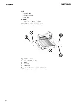
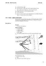
1

2

Fig. 34: Remove the cover

1 Remove the cover screws

2 Cover

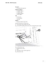
3.

Remove five screws from the right cover.

4.

Remove the cover.

Summary of Contents for Hammer HNC3 825

Page 1: ...to hand and in good condition for future reference Please read this operating manual carefully before using the machine Translation of the original operating instructions HNC3 825 HNC3 825 perform CN...

Page 2: ...2022 FELDER KG KR Felder Stra e 1 A 6060 HALL in Tirol AUSTRIA Telephone 43 5223 5850 0 Email info felder group com Internet www felder group com...

Page 3: ...quipment 10 2 7 Other risks 11 2 7 1 Transport setup installation and disposal 13 2 7 2 Operate maintain and troubleshoot 14 2 8 Foreseeable misuses 15 3 Declaration of Conformity 17 4 Technical infor...

Page 4: ...t the extraction hood 47 9 Use 48 9 1 Switch on the machine 48 9 2 Operate machine 49 9 3 Switch off the machine 50 9 4 Processing information 50 9 4 1 Compensate for any bend in the workpiece 50 9 4...

Page 5: ...ation of immediate danger which will result in death or severe injuries if it is not avoided WARNING indicates a situation of possible danger which can result in death or severe injuries if it is not...

Page 6: ...raphics are not depicted on a 1 1 scale The product that has been delivered may have custom built specifications add on options or recent technical modifications and may therefore deviate from the des...

Page 7: ...nted person is familiar with the operation of such a machine or a similar one or has been trained by the manufacturer Knowledge about the contents of this manual is a prerequisite for protecting perso...

Page 8: ...be operated if it is in proper working order and in safe condition The general condition of the machine must be checked and the machine must be inspected for visible defects each time before it is sw...

Page 9: ...the machine that might compromise safety to the operator 2 4 Making changes and modifications to the machine In order to avoid potential hazards and to ensure optimum performance no modifications alt...

Page 10: ...oose hair is forbidden With long hair and beards a hair net must be worn Wearing of jewellery Necklaces watches rings long earrings etc forbidden 2 6 2 Mandatory safety equipment When working on or wi...

Page 11: ...ow to operate the machine and are in strict observance of all safety instructions If possible only perform work when the machine is disconnected from all energy sources and an unintentional restart is...

Page 12: ...ommissioned safety devices can cause severe injury Do not deactivate or bypass protective devices Foreign bodies in the materials to be processed Foreign bodies in the materials to be processed can ca...

Page 13: ...Ensure that chains belts and ropes do not lie against sharp edges Improper setup and installation Serious injuries and material damage Machine may only be set up by authorised trained personnel who a...

Page 14: ...owed ambient temperature Surpassing or falling below the allowed temperatures can cause malfunctions of the machine and unpredictable machine movements which can lead to severe personal and material d...

Page 15: ...if the operation manual is not complete or is not available in the language of the country it is being operated in Placing objects or tools on the work surface Use of tools or materials which are not...

Page 16: ...16 Safety instructions Maintenance misapplication Service work carried out by untrained or unauthorised personnel Non observance of the maintenance guidelines Non observance of usage and damage tracks...

Page 17: ...guidelines see table Manufacturer Felder KG KR Felder Stra e 1 6060 Hall in Tirol Product designation CNC portal machine Manufacturer Hammer Model type HNC3 825 The following EC guidelines were appli...

Page 18: ...e 1 6060 Hall in Tirol Product designation CNC portal machine Manufacturer Hammer Model type HNC3 825 The following EC guidelines were applied S I 2008 1597 Supply of Machinery Safety Reg ulations 200...

Page 19: ...e and extrac tion hood Machine Data Value Unit Total length 1111 mm Total width 766 mm Total height 685 mm HNC3 825 weight approx 85 kg HNC3 825 perform weight approx 103 kg Packaging including machin...

Page 20: ...mm Portal clearance height 160 mm Table surface 1005 x 574 mm T grooves in the table for M6 17 5 x 7 5 mm Drive spindle Z axis trapezoidal threaded spindle 14 x 6 mm Drive spindle X Y axis ball screw...

Page 21: ...ine zero point is situated at the rear left hand corner Rear Main switch power connection X axis Y axis Z axis Positive limit 825 00 479 00 160 00 Negative limit 0 00 0 00 0 00 Reference point 798 00...

Page 22: ...technolog ical parameters need to be correctly selected Incorrect parame ters lead to poor results The performance of the machine indi cated can only be achieved through the use of the Eding Con troll...

Page 23: ...aterial Soldered tools and tools that have a diameter larger than 8 mm may only be used with protective housing Chapter 5 1 3 Protective housing on page 30 Single component tools with a diameter of up...

Page 24: ...ntrol 0 10 volt 4 Connection machine head 5 Extraction cable guide Data Value Unit Connection on the machine C14 device plug AC input voltage machine 88 264 V Frequency 50 60 Hz Max power consumption...

Page 25: ...g Input voltage frequency converter HNC3 825 perform switch box 200 240 V Frequency 50 60 Hz Max power consumption FC electrical cabinet HNC3 825 perform 2300 W The HNC3 825 perform must be equipped w...

Page 26: ...asurement uncertainty factor of 4 dB A Meas urement conditions and additional information according to ISO 19085 1 2021 chapter 6 2 2 The measurements are carried out in accordance with the following...

Page 27: ...se emission as low as possible always use sharpened tools and operate the machine at the correct speed The machine s maintenance and the type of workpiece to be processed also affect the noise emissio...

Page 28: ...is 2 Workpiece support 3 Mains connection main switch 4 Portal with machine head 5 Working head 6 Router spindle fixation 7 Emergency stop connection PC 4th axis AUX 5 1 Safety devices 5 1 1 Main swit...

Page 29: ...in switch 1 Machine main switch 2 Frequency converter main switch Two main switches for both the machine and the frequency converter are located at the back of the machine Position O OFF Mains voltage...

Page 30: ...will stop The emergency stop button is unlocked by turning Fig 8 Emergency stop button 5 1 3 Protective housing In order to ensure that the machine can be safely worked with the protective housing mu...

Page 31: ...ness 19 mm Material MDF 5 2 Pictograms signs and labels All the pictograms signs and labels affixed to the machine must be kept visible readable and must not be removed 1 2 3 4 2 Fig 10 Pictograms sig...

Page 32: ...Information on the machine data plate 1 2 3 4 5 6 Fig 11 Information on the machine data plate 1 Manufacturer information 2 Model type 3 Machine number 4 Electrical connection 5 Year of build 6 Additi...

Page 33: ...ing them according to type and size for recycling Environmental protection Packaging materials are valuable raw materials and in many cases they can be used again reprocessed or recycled Keep transpor...

Page 34: ...oid extreme temperature fluctuations condensation build up Apply a coat of oil to all exposed machine parts corrosion protection Regularly check the general condition of all parts and the packaging du...

Page 35: ...ructions Or alternatively you can use this link http fg am hncfirststeps Fig 12 Packaging Personnel Trained machine operator Protective equipment Protective clothing Protective gloves Protective footw...

Page 36: ...e is attached to the pallet with 2 transport brackets 1 2 3 Fig 13 Transport bracket 1 Transport bracket 2 Screws 3 Screws Personnel Trained machine operator Additional assistant Protective equipment...

Page 37: ...n Do not stop below suspended loads Keep enough distance to the machine during transport Transport the machine as carefully as possible Chains belts ropes or other hoisting devices must be equipped wi...

Page 38: ...r Additional assistant Protective equipment Protective clothing Protective gloves Protective footwear Tool Spirit level An additional assistant is needed 1 Bring the machine to the site of installatio...

Page 39: ...2 3 4 Fig 16 Dust extraction hood HNC3 825 perform 1 Dust extraction hood 2 Height adjustment screw 3 Magnetic dust brush 4 Extraction connection 1 Mount the extraction hood to the machine head using...

Page 40: ...on a daily basis and the efficiency on a monthly basis Use extraction with reduced dust emission to clean dust from the machine Connection to the dust extraction system 1 2 3 Fig 17 Attach the dust ex...

Page 41: ...ust be switched off Overview 1 2 3 4 5 Fig 18 Machine connections at the front 1 PC Port 25 Pin 2 Emergency stop 3 Tool length measuring system 4 4th axis 5 AUX Port 4 1 2 5 3 Fig 19 Connect electrics...

Page 42: ...ed to the machine 1 2 Fig 20 Connect frequency converter HNC3 825 perform 1 Mains connection C14 2 Main switch NOTICE Incorrect mains frequency Damage to the HF spindle The HF spindle must always have...

Page 43: ...supply 2 Connect the emergency stop button to the emergency stop connection Connect the PC for Eding CNC The PC must be connected to the machine using the PC Port 25 pin 1 Fig 22 Connect the PC 1 PC...

Page 44: ...ing voltage is the same as the input voltage of the machine 1 Place the router motor in to the 43 mm collar and clamp using the nut 10 11 Nm 2 Connect the power cable and rotation speed control option...

Page 45: ...trolled with controllers and software of various manufac turers However the machine performance stated can only be achieved with Eding CNC The correct functioning cannot be guaranteed of controllers o...

Page 46: ...machine or changing the tools may only be done once the machine has stopped Beware of any possible collisions with stops and workpieces Wear protective gloves Tools can become hot when being used Tool...

Page 47: ...until it reaches the stop in the tool socket 4 Tighten the HF spindle with a spanner 5 Tighten the locking nut and check that the router tool is inserted correctly 8 2 Adjust the extraction hood 1 2...

Page 48: ...e machine is ready to operate Warm up the HNC3 825 perform The spindles of the HNC3 825 perform must be warmed up if the ambient temperature is below 17 C machine is new Within the first 5 days of ope...

Page 49: ...operty Use appropriate clamping devices to fasten the workpieces to the machine table 1 Loading G Code in the operation software 2 Fix workpieces to the machine table using suitable clamping devices I...

Page 50: ...ble the frequency converter 9 4 Processing information 9 4 1 Compensate for any bend in the workpiece If the workpiece is bowed then clamp it with the bow facing upwards If locking holes are drilled f...

Page 51: ...regular intervals If there is a lot of dust or noise then the machine must be lubricated NOTICE Incorrect lubricant lack of lubrication Material damage defect bearings machine does not function as it...

Page 52: ...ning cloths Hex key Material Lubricant Interflon Grease HD2 Interval Twice a year or if noises occur 3 2 2 1 4 Fig 31 X axis cover 1 Front side of the machine 2 Screws 3 Cover left 4 Cover right 1 Loo...

Page 53: ...3 Switch off the machine at the main switch disconnect the power supply 4 Remove dirt or grease 5 Clean all lubricating nipples 6 Place the pressure grease gun onto the nipple and pump 3 times A small...

Page 54: ...off the machine at the main switch disconnect the power supply 2 Remove visible dirt or grease 3 Clean lubricating nipple 4 Place the pressure grease gun onto the nipple and pump 3 times A small amou...

Page 55: ...oggles Tool Grease gun Cleaning cloths Hex key Material Lubricant Interflon Grease HD2 Interval Twice a year or if noises occur 1 Position the working head on the right 2 Switch off the machine at the...

Page 56: ...nipple and pump 3 times A small amount of lubrication will come out of the seals 7 Repeat the process for both lubricating nipples 8 Switch machine on 9 Position the working head on the left and repe...

Page 57: ...e gloves Protective footwear Safety goggles Tool Cleaning cloths Brush Material Lubricant Interflon Grease HD2 Interval Every 20 hours or if noises occur 1 Move the machine head into the lowest positi...

Page 58: ...ch of the Z axis guides 1 Fig 37 Lubricate guides 1 Lubricating nipple Personnel Trained machine operator Protective equipment Protective clothing Protective gloves Protective footwear Safety goggles...

Page 59: ...n film of grease 10 3 Check replace the drive belt The drive belts are wear and tear parts and must be checked regularly The belt tension must be checked regularly If the belt tension is too high or t...

Page 60: ...de 2 Remove worn out damaged belts and dispose of correctly 3 Fitting a new belt 4 Move the motor with one hand away from the axis and then fix the locking screws The belt tension needs to be between...

Page 61: ...l using clamps This will ensure that the portal remains parallel 1 2 3 3 Fig 40 X axis cover 1 Screws 2 Cover 3 Clamp position 4 Remove the cover screws and carefully detach the cover Pay attention to...

Page 62: ...lt over the outer wheels and insert into the drive motor as shown 3 Loosen the belt tensioning screws and tighten the belt The belt tension needs to be between 37 to 41 Hz 4 Fix belt tensioner 6 Screw...

Page 63: ...5 Fig 42 Portal cover 1 Portal screws 2 Cable guide 3 Hex key 4 Z axis cover 5 Portal cover 2 Loosen the hex screw and remove the Z axis cover 3 Remove the portal screws and cable guide 4 Remove the p...

Page 64: ...ove them Support the opposite side 2 Remove the old belt and dispose of correctly 3 Fitting a new belt 4 Move the motor with one hand away from the axis and then fix the locking screws The belt tensio...

Page 65: ...whether the malfunction and cause of the malfunction have been professio nally remedied 2 whether all safety equipment has been installed in accordance with regula tions and are technically and funct...

Page 66: ...movement incor rect dimensional deviations Other controller software than Eding CNC is being used Check the parameter and adjust Use EdingCNC con troller software Unusual noises vibrations Drive spind...

Page 67: ...thorised for use are listed in a separate spare parts catalogue enclosed in the docu mentation package supplied with the machine Spare part order 3 4 1 2 Fig 44 Spare parts Order 1 Model type 2 Machin...

Page 68: ...chine components into material groups 3 When disposing pay attention to international regulations standards and environmental protection norms ENVIRONMENT Disposing of batteries Batteries are subject...

Page 69: ......

Page 70: ...FELDER KG KR Felder Stra e 1 A 6060 HALL in Tirol AUSTRIA Telephone 43 5223 5850 0 Email info felder group com Internet www felder group com...

Reviews: