


Diesel engine Series 15B / 18B
Installation and commissioning
42
2008-09-08
Fig. 19
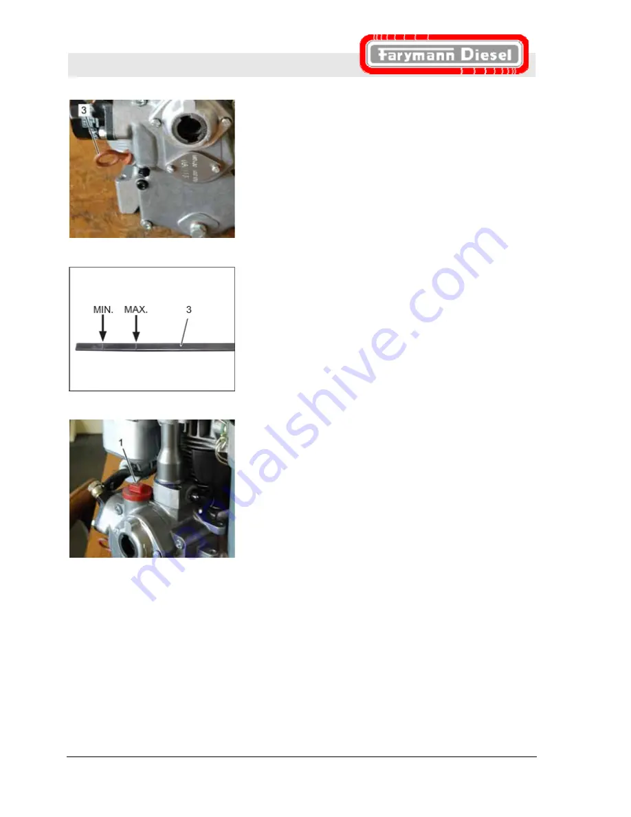
3.
Pull out oil dipstick (3) and clean the bottom end with a clean
and fluff-free cloth.
4.
Replace the oil dipstick (3) and pull it out again.
Fig. 20
5.
Check the oil level quantity. The oil level should be just under
the Max. marking.
6.
Fill with engine oil if needed.
Fig. 21
7.
Only tighten the oil filler cap (1) by hand (risk of breakage).
Pos: 6.12 /KN2006-SM/nL.......... Seitenumbruch .......... @ 8\mod_1141998334703_0.doc @ 75491


