Operating manual
CNC 8055
CNC 8055i
O
PERATING
IN JO
G MODE
2.
·TC· O
PTION
S
OFT
: V02.2
X
·41·
Zero offs
et
table
2.4
Zero offset table
It is possible to manage the zero offset table from the conversational mode (G54.... G59, G159N7
... G159N20). This table contains the same values as that of the conversational mode.
Press the [ZERO] key to access the zero offset table as well as to get out of it. The zero offset table
may be accessed in the following ways.
• From the standard screen, as long as no axis is selected. The CNC will request confirmation
of the command.
• From ISO mode, when the "zero offsets and presets" cycle is selected.
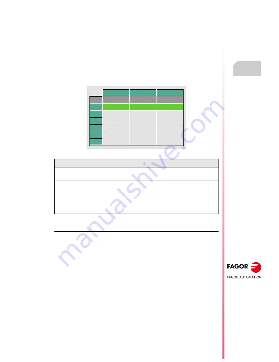
The zero offset table looks like this. It shows all the offsets, PLC offset included, and their value in
each axis.
When scrolling the focus through the table, the elements appear in different colors as follows.
How to edit the table data
The following operations are possible in the zero offset table. Press [ENTER] to validate any
changes.
• Editing a zero offset.
It is edited one axis at a time. Select a data with the focus and edit its value. If the magnifying
glass is placed on top of an offset (G54 ... G59, G159N7 ... G159N20), editing start on the first
axis of that offset.
• Load the active zero offset into the table.
Position the magnifying glass over the offset you wish to define (G54 ... G59, G159N7 ...
G159N20) and click on the [RECALL] key. The active preset is saved in the selected zero offset.
If instead of placing the focus on a zero offset, it is placed on one of the axes, only that axis will
be affected.
• Deleting a zero offset.
Position the magnifying glass over the offset that you wish to erase (G54 ... G59, G159N7 ...
G159N20) and click on the [CLEAR] key. All the axes of that zero offset are reset to zero.
If instead of placing the focus on a zero offset, it is placed on one of the axes, only that axis will
be affected.
Color
Meaning
Green background.
Text in white.
The real value of the table and the value shown on the screen are the same.
Red background.
White text.
The real value of the table and the value shown on the screen are NOT the same.
The value on the table has been changed, but it has not been validated. Press
[ENTER] to validate the change.
Blue background.
The zero offset is active.
Two origins may be active simultaneously, one absolute (G54 ... G57, G159N7
... G159N20) and another incremental (G58-G59).
PLC
G54
G55
G56
G57
G59
G58
X
Z
V
0.0000
0.0000
0.0000
0.0000
0.0000
0.0000
0.0000
0.0000
0.0000
0.0000
0.0000
0.0000
0.0000
0.0000
0.0000
0.0000
0.0000
0.0000
0.0000
0.0000
0.0000
Summary of Contents for 8055 FL
Page 1: ...CNC 8055 TC Operating manual Ref 1711 Soft V02 2x...
Page 6: ...6 Operating manual CNC 8055 CNC 8055i SOFT V02 2X...
Page 10: ...10 CNC 8055 CNC 8055i Declaration of conformity and Warranty conditions...
Page 14: ...14 CNC 8055 CNC 8055i Version history...
Page 20: ...20 CNC 8055 CNC 8055i Returning conditions...
Page 22: ...22 CNC 8055 CNC 8055i Additional notes...
Page 24: ...24 CNC 8055 CNC 8055i Fagor documentation...
Page 180: ...180 Operating manual CNC 8055 CNC 8055i 4 Y AXIS TC OPTION SOFT V02 2X Tool calibration...
Page 207: ...Operating manual CNC 8055 CNC 8055i 7 SOFT V02 2X 207...
Page 208: ...208 Operating manual CNC 8055 CNC 8055i 7 SOFT V02 2X...
Page 209: ......


