background image

5

-19

Maintenance

5


3


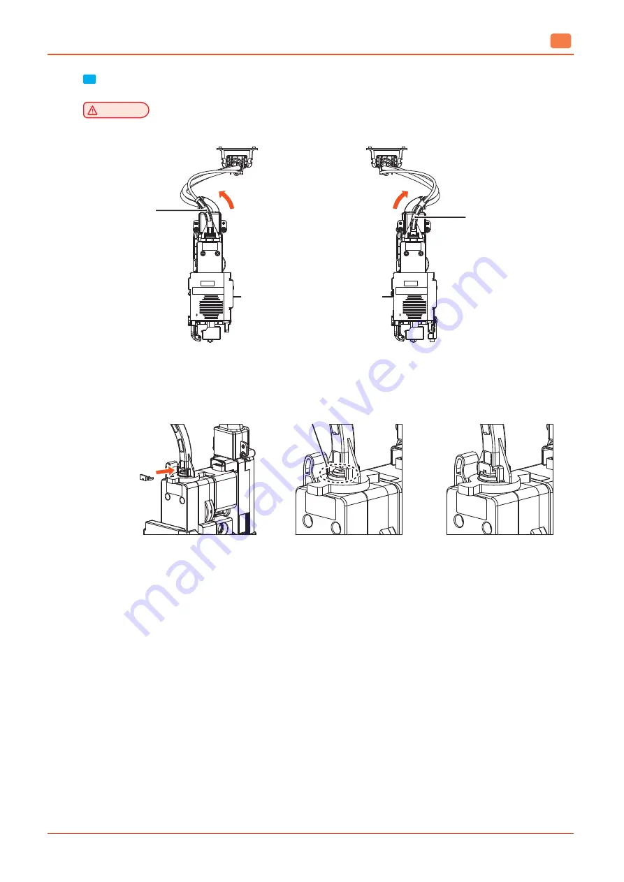
Assemble the snap rings after positioning the tube guides as shown in the figure below.


Caution


-  If the snap ring comes off, the tube guide will not be fixed properly.

Tube Guide

Direction

(Nozzle #1)

Tube Guide

Direction

(Nozzle #1)

Tube Guide

Tube Guide

Nozzle #1

Nozzle #2

Snap ring assembly location

(Between the fitting and tube holder)

Assemble Snap-ring

Assembling completed

Summary of Contents for A530

Page 1: ...fabweaver com Please read the user manual before using the product and keep the manual in an easily accessible place This image is with the optional station installed User Manual type A530 ...

Page 2: ... instructions may lead to death or serious injury Caution Failure to observe instructions may cause injuries or damages to property Connect the power cord directly to the wall outlet Do NOT use an extension cord If the power cord or plug has been eroded or damaged pull the plug to remove it Do NOT remove covers or screws unless otherwise stated in this manual in order to avoid electric shocks or b...

Page 3: ...damages caused by the improper handling and operation of this pro duct or consequential damages caused by the user s negligence 3 Copyrighted materials may be printed for personal use or at home within the scope permitted by applicable laws Other illegal reproduction is prohibited by law 4 The above description is an example only and may not include the whole content We hold no liability for its a...

Page 4: ... Flash Drive 16 11 1 Notice for Electromagnetic Interface EMI 16 11 2 How to Use the USB Flash Drive 17 11 3 USB Certification Information 17 Chapter 1 Preparation for Use 1 Specifications 1 2 1 1 Printing 1 2 1 2 Temperature Speed 1 2 1 3 Main Body 1 2 1 4 Software Support 1 2 1 5 Default of Print Layer Width 1 2 2 Basic Components 1 3 3 Component Name 1 4 4 Installation Power Supply Filament Box...

Page 5: ...leting a File from Queue 2 8 Changing File Order 2 8 2 3 Materials 2 9 Screen Configuration 2 9 Nozzle Information Checking 2 10 Material Loading 2 10 Material Unloading 2 12 2 4 Tools 2 13 Screen Configuration 2 13 XYZ 2 13 Extruder 2 14 Nozzle Change 2 15 Nozzle Tip Cleaning 2 17 Nozzle Auto Cleaning 2 19 Chamber Cleaning 2 20 Self Check 2 21 Bed Leveling 2 21 Nozzle Calibration 2 22 Z Offset 2 ...

Page 6: ...Cleaning 5 2 Nozzle Tip Cleaning 5 3 Cleaning Pad 5 4 1 2 Regular Inspection 5 7 Inspecting Oil Grease 5 7 1 3 Cleaning of Flexible Bed and Nozzle 5 7 2 Error Messages and Solutions 5 8 3 Troubleshooting 5 9 3 1 How to Handle Error 401 5 9 3 2 How to remove filament fragment 5 14 How to remove filament fragment from the junction 5 14 How to remove filament fragments from the tube connection of the...

Page 7: ...4 3 Spool Replacement 5 23 4 4 Nozzle Change 5 27 4 5 How to release the front door lock when it operates abnormally 5 32 4 6 How to solve when the front door doesn t lock 5 33 Chapter 6 Appendix 1 Filament Type Material Color 6 2 ...

Page 8: ......

Page 9: ...tion is prohibited by law The above description is an example only and may not include the whole content We hold no liability for its accuracy and completeness Should you have questions about the legality of printing an object please seek legal advice Note Features of the product described in this manual may differ from the actual product you receive Some options may not be available in some count...

Page 10: ...Indicates cautions for using this product regarding filament supply errors or data loss etc Please carefully read the instructions Symbols indicate the information required before operating this product Note Symbols indicate the description of product functions and the actions against user errors Reference This symbol is at the end of a paragraph It indicates the location of related description Th...

Page 11: ...e power is off first Unplug the power cord and wait until the bed and nozzle cool down to room temperature Caution Electric Shock Contact with this part may cause pain Follow the instructions below to avoid pain or product damage Do NOT open the front and top doors when this product is in operation Do NOT touch any parts of this product except the bed when the power is on If you need to touch any ...

Page 12: ...the power cord stripped off or overloaded Do NOT have the power cord get jammed into any gaps between furniture and wall Improper use of the power cord may cause fire or electric shock Check the power cord regularly Before inspecting this product disconnect the power cord from the outlet first For any problems not described in this manual contact an expert Caution Risk of pain Putting your head in...

Page 13: ...ace adequate ventilation is needed Place the product on a firm table that can sufficiently support its load Important Install the product so that the vents is kept at least 10 cm away from the wall or surrounding devices Secure proper space around the product for easy ventilation and operation Use the product in an environment at a temperature of 16 29 and humidity of 20 70 RH Do NOT install or us...

Page 14: ...ower cord from the outlet and check if it is disconnected from the printer When lifting this product be careful not to damage your spine by bending your knees sufficiently When moving the product hold the handle on the upper section of this product When carrying the product by packing or long distance repack it in the original box while placing the product with the bottom facing down for safe tran...

Page 15: ...witch is rotated 90 degrees counterclockwise so that the horizontal straight bar indicates ON Do not confuse the meaning with the horizontal straight bar Switch standard IEC 61058 1 Operating direction for OFF or OFF position Circle Operating direction for ON or ON position Straight bar Warning Do NOT touch the power switch with wet hands when connecting or disconnecting the power cord It may caus...

Page 16: ...and lose its ability to dehumidify If the filament and desiccant are exposed to moisture you can use the printer s chamber preheat function to restore performance After setting the chamber preheat temperature according to the type of filament put the filament in the chamber to dry it ABS ASA RSA over 12 hours at 60 C PLA 4 5 hours at 40 C After recovering the filament desiccant by using the chambe...

Page 17: ...re very hot when this product is in operation When removing an output or examining the inside the product be careful NOT to touch the nozzle and bed It may cause burns Do NOT operate this product in a way not described in this manual Do NOT open the door while this product is in operation ...

Page 18: ...ce 1 Consider the indoor space and use an indoor fan with an appropriate capacity 2 Turn on the fan before operating the 3D printer and run the fan for at least 1 hour after using the 3D printer 3 Do not completely close the door while the fan is running but leave it slightly open 4 Use of a fan should be combined with natural ventilation Indoor ventilation Natural ventilation 1 In spring and autu...

Page 19: ... Rules These limits are designed to provide reasonable protection against harmful interference in a residential installation This equipment generates uses and can radiate radio frequency energy and if not installed and used in accordance with the instructions may cause harmful interference to radio communications However there is no guarantee that interference will not occur in a particular instal...

Page 20: ...been connected to the outlet but the power switch is on 0 7W Off Mode The power plug has been connected to the outlet but the power switch is off 0 5W The power consumptions listed in the above table are average measurements over time Instantaneous power consumption may be considerably higher than the average Inactive Mode Products with Inactive mode may still consume small amount of power even in...

Page 21: ...l of Used Battery There are lithium batteries in the control board of this product Used batteries need to be disposed of in an eco friendly way according to the manufacturer s instructions To replace batteries contact a service technician ...

Page 22: ...gh temperature or fire Warning We are not liable for any damages or losses caused by unauthorized modification Caution This module is so mounted that the possibility a person contact with it is minimized to prevent he or she from being exposed to radio waves that exceed FCC RF exposure limits Important Frequency IEEE 802 11b 2412MHz 2462MHz IEEE 802 11g 2412MHz 2462MHz IEEE 802 11n 20MHz 2412MHz 2...

Page 23: ...g 11 IEEE 802 11n 20MHz 11 IEEE 802 11n 40MHz 7 Modulation IEEE 802 11b DSSS CCK IEEE 802 11g OFDM IEEE 802 11n 20MHz OFDM IEEE 802 11n 40MHz OFDM Power Consumption 5V 500mA Maximum Dimensions 48 0 mm X 28 0 mm X 3 7 mm Operating Temperature 0 60 C Storage Temperature 10 80 C ...

Page 24: ...harmful interference to radio or television reception which can be determined by turning the equipment off and on the user is encouraged to try to correct the interference by one more of the following measures Reorient or relocate the receiving antenna Increase the separation between the equipment and receiver Connect the equipment into an outlet on a circuit different from that to which the recei...

Page 25: ...CD screen may blink due to static electricity There is no problem with machine operation and safety USB Flash Drive USB Port Location 3 Select a file to print by operating the UI on the LCD screen Note For the information on printing see 1 Printing on page 3 2 11 3 USB Certification Information Information on the USB flash drive Model 32GB MB032 Brand fabWeaver Manufacturer Shenzhen Chenge Electro...

Page 26: ......

Page 27: ...Preparation for Use 1 type A530 ...

Page 28: ...mperature 110 Max Printing Speed 200 mm s Continuous operation at max temperature may cause malfunctions Please set in a special case such as nozzle clogging and other troubles 1 3 Main Body Power Max 1050W Dimension mm 747 x 810 x 784 W x D x H Weight 112kg Port USB devices USB hosts Wi Fi Ethernet Filament Auto load Unload 1 4 Software Support Software Weaver3 Studio File Format w3s stl ply obj ...

Page 29: ...ox 2x Scrapper Cleaner Tube Installation Guide Filament Box Label Nozzle Cleaning Spring Power Cord USB Flash Drive Cable and Tube for Connecting Filament Box 2x Nozzle Cleaner Brush Small Nozzle Cleaning Tool Nipper Nozzle Cleaner Brush large Hex Key Warning The scrapper blade is very sharp Please be careful when using the scrapper Do NOT use for any other purpose than removing outputs In particu...

Page 30: ...for a few seconds after the power cord is disconnected Lamp Off Inactive mode Power cord is disconnected 3 USB Port To connect a USB flash drive that contains a file to print it 4 Front Door Handle To open the front door 5 Top Door Handle To open the top door 6 Filament Box Connection Open the cover to connect the main body to the filament 7 Carrying Handle To hold and carry the printer 8 Main Pow...

Page 31: ...he flexible bed 4 Bed Leveling Knob Knobs for leveling the bed 5 Cleaning Duct It is a space that guides the fused filament to the bottom of the chamber during the nozzle cleaning operation Periodically clean the filament debris on the chamber floor 1 2 4 5 6 Nozzle Nozzle Core 3 8 7 No Name Description 1 Fan 1 Cooling fan for output 2 Fan 2 Cooling fan for nozzle heat sink 3 Filament Pressure Lev...

Page 32: ...replaced 1 2 3 4 5 6 Front of Filament Box Back of Filament Box No Name Description 1 Cover Opening Closing Lever Used to open close the box cover 2 Spool Lock Lever Used to lock and fix the spool when it is installed Pull the lever to unlock the lever 3 Filament Insertion To load a filament insert it in this location 4 Motor Cable Port To connect the motor cable to the main body 5 Filament Fittin...

Page 33: ...ge 7 4 2 Filament Box Installation 1 Prepare the filament box tube and cable 2 Connect the cables according to the color indicated on the label on the back of the filament box Insert the tube up to the marked position on the end of the tube as shown Assemble both filament boxes identically BLACK BLUE Connect Blue Cable Connect Black Cable Insert Tube BLACK BLUE Tube Insertion Only One Location Dis...

Page 34: ...ng to color codes of the filament box connectors Insert the tube up to the marked position on the end of the tube as follows Tube Insertion Two Locations Displayed Connect Blue Cable Insert Tube Connect Black Cable Caution The cable and tube from one filament box should be connected to either the top or the bottom Do Not connect them to the top and the bottom If the cable and tube from one filamen...

Page 35: ...2 differ correctly attach the labels by checking the locations connected to the main body 1 Label 2 Label 6 Turn the power supply on and install a spool on the filament box Reference For the information on how to install a spool see 4 3 Filament Replacement on Page 5 12 5 4 3 Program Installation Download the Weaver3 Studio installation program from the USB flash drive or our website and execute i...

Page 36: ...e after purchasing the product you can proceed with the initial setup by following the steps below 1 Choose the language you want to use and then press the Next button 2 Select a time zone from the list or enter a time zone in the search field to select a time zone and then press the Next button ...

Page 37: ...abWeaver The collected user data is used to improve the user experience and continuously improve the product Participation is optional but you can change your participation at any time in the Settings menu 4 You can set the product name and security settings Security settings can restrict arbitrary manipulation by other users After entering the setting values press the Next button Reference The in...

Page 38: ...work settings Press Skip if you want to configure the network settings later 6 Check whether the product has software updates If there is no network connection the update cannot proceed Press the Finish button to finish the initial setup and reboot the product ...

Page 39: ...UI Menu Description 2 type A530 ...

Page 40: ...y its Details page on the right of the screen Icon Name Description Print To use the functions related to printing Queue To manage the list of files to be printed in queue Material To check the information on nozzles and materials installed in the printer and opera te the function of loading unloading materials Tools To operate the function of maintaining and calibrating the printer Settings To co...

Page 41: ...hamber Display the material and remaining amount of the filament 2 Time and Connection Status Display Display the current time and various connection status set on the printer USB Memory Connection Not connected Connected Important During the file transfer the icon will blink and a message will be displayed Do not remove the USB memory while the message is displayed Wifi Connection Not connected C...

Page 42: ...scription 2 4 2 1 3 Navigation Bar The location of the menu currently displayed can be checked and additional functions can be operated 1 4 Details Screen The Details screen of the selected function is displayed ...

Page 43: ...aning Chamber Cleaning Self Check Calibration Bed Leveling Nozzle Calibration XY Calibration Enter Calibration Value Z Offset Auto Calibration Additional Calibration Test Print Settings Language Unit Time Settings Network Cloud Security Volume Smart Power Management Chamber Preheating Power Saving Wake Up Lamp Camera Frame Rate Open Material Status Bar Information Name Password Change Update Check...

Page 44: ...reen Configuration In the default screen a user can check the printer name and the material information loaded Press the Load button to select a file File Import 1 Press the Load button in the default screen to import a file Press the USB and Internal button to check the location where the file is saved ...

Page 45: ...st of the queue in the order they are sent from a PC or the Print menu The order of files in the queue can be changed and a file can be added or deleted Screen Configuration A user can check the list of files in queue on the right of the screen Select a file to check the shape of the output on the left of the screen If nothing is printed the file most recently printed is displayed on the top of th...

Page 46: ...Press the Edit button on the upper right of the screen and select a file Press the Delete button on the bottom After the action is done press the Complete button Changing File Order Press the Edit button on the upper right of the screen Press and hold the icon to the right of the file name and move up or down the icon to change the file order After the action is done press the Complete button ...

Page 47: ...oading a material Screen Configuration In the initial screen a user can check the type color remaining amount and load status of a material in each nozzle Press the Nozzle button on the top to check the nozzle information or press the Spool button to load or unload a material Display Description Spool not mounted Unloaded Half loaded Loaded ...

Page 48: ...nformation on nozzle types usages etc Material Loading 1 Install the spool in the filament box and insert the filament into the filament insertion hole inside the filament box Half loading will then start automatically Reference For the information on how to install a spool see Spool Replacement on Page 5 11 ...

Page 49: ...ad button 3 Check if the tube is properly inserted to the nozzle and if there are debris on the bed Press the Next button to start the loading 4 The printer automatically inserts the filament up to the nozzle Once the loading is completed the previous screen is displayed ...

Page 50: ... Check if the tube is properly inserted to the nozzle and press the Next button 3 The printer automatically removes the filament Once the unloading is completed the previous screen is displayed Reference For the information on how to remove a spool after unloading see 4 3 Spool Replacement on Page 5 11 ...

Page 51: ...n Management sub menu there are options to maintain the printer In Calibration sub menu there are options to calibrate the nozzle and the bed XYZ The nozzle and the bed can be moved to a desired location Press the Nozzle 1 or Nozzle 2 button to select a nozzle to move Select a desired value and press a arrow Click the All X Y or Z buttons on the bottom to move to the home location of each directio...

Page 52: ...e is automatically heated first If the nozzle reaches its target temperature the filament transfer can be operated Press the Cancel button when the nozzle is heated to exit from this menu Press the Nozzle 1 or Nozzle 2 to select a nozzle Select a value to transfer the filament and press a arrow to transfer it to the desired direction ...

Page 53: ... the filament before replacing it For safety it is recommended to replace the nozzle while the power is off Caution When the nozzle is heated the part is very hot Be careful not to burn yourself 1 Press the Nozzle 1 or Nozzle 2 button to select the nozzle to be replaced and then press the Next button 2 Press the Nozzle Disconnect button to disconnect the nozzle ...

Page 54: ... replacing the nozzle refer to P 5 21 4 4 Nozzle Change 4 After installing the nozzle press the Nozzle Connect button to reconnect the nozzle Reference The combinations of nozzles that can be installed on Nozzle 1 and Nozzle 2 are as follows Check the label attached to the front of the nozzle Nozzle1 Nozzle2 ABS ASA SUPPORT PLA PLA ...

Page 55: ... a risk of burns To avoid burns wear protective equipment before cleaning the nozzle 1 Prepare the nozzle cleaning brush and then press the Next button to prepare the nozzle tip cleaning 2 The nozzle automatically moves to a position that is easy to clean 3 The nozzle is heated so that foreign substances adhering to the tip of the nozzle can be easily removed Wait for the nozzle to heat up to the ...

Page 56: ...ozzle overheating it automatically moves to the finishing step after 10 minutes Caution Be careful not to damage the silicone adhesive between the nozzle and the silicon cap Be careful not to damage the silicone adhesive between the nozzle and the silicon cap 5 In the final step the nozzle heater is turned off to finish cleaning Caution Even if the nozzle heater is off the parts will be very hot i...

Page 57: ... filament 1 Automatically remove the filament residue left inside the nozzle Press the Nozzle 1 or Nozzle 2 to select a nozzle to clean and press the Next button 2 Before cleaning the nozzle the nozzle is heated If the nozzle reaches its target temperature it is automatically cleaned ...

Page 58: ...moved up and down to clean the inside of the chamber Press a arrow button to slightly move the bed up or down Caution Be careful NOT to have your body parts caught while the bed is operated In addition do NOT excessively move the bed The product may be damaged ...

Page 59: ... printer are normally operated Bed Leveling 1 The bed can be leveled by measuring the degree of inclination of the bed Press the Check button to start the measurement 2 Turn the leveling knob on the bottom of the bed as many as the clicks displayed in the screen Press the Check Again button to measure is again ...

Page 60: ...nt they should print on the same coordinates Important If the positions of Nozzle 1 and Nozzle 2 are incorrectly calibrated the print quality may be affected 1 Press the XY Calibration button to print the pattern for calibration Note Press the Enter Calibration Value button Then a value for calibration can be directly entered without printing the pattern for calibration ...

Page 61: ...s 1 and 2 If there are no straight lines enter the number of lines most approximate to a straight line After entering the value press the Save button to print the pattern again to check Note The X axis value is 0 at the center 10 at the left end and 10 at the right end The Y axis value is 0 at the center 10 at the top and 10 at the bottom ...

Page 62: ...on the tip of the nozzle can interfere with the measurement and cause inaccurate height calibration Note The auto calibration operation may take some time as it includes nozzle cleaning operation and preheating operation It is recommended to perform automatic calibration in the following situations When the printer is installed for the first time If you replace the nozzle If you have moved the pri...

Page 63: ...tively and press the Save button Important If the average value is within 0 05 mm of the reference value of 5 mm no further adjustment is required and no value entry is required Nozzle1 Nozzle2 Nozzle1 Nozzle2 Note You can touch the number of the input field to enter the value directly or touch the or buttons to adjust the value you want to input The additional calibration value that you saved is ...

Page 64: ... the security setting unauthorized operations by another user can be restricted On Off Volume The buzzer sound level of the printer can be adjusted Off Min Med Max Smart Power Management Set the printer s power management See Smart Power Management on Page 2 26 Lamp Set the operation of an internal lamp Note The lamp is turned on when the web monitor is connected Always On On during Print Always O...

Page 65: ...network is connected the printer time can be synchronized with the Internet time by pressing the On button to synchronize times Or press the Off button from the Internet Time field to cancel the synchronization and directly adjust the time In the Time Zone field press the arrow button to display the detailed settings Set a region to change the time zone ...

Page 66: ... to connect To connect a wired network using LAN press the Wired tab To use a dynamic IP press the arrow button on the right of the DHCP option To use a static IP press the arrow button on the right of the Static option and enter the IP If you press the Connection methods button you can select the network connection method among wired wireless or wired wireless If you use both wired and wireless y...

Page 67: ...for the first time the printer should be registered with the cloud server to use the service 1 Enter the printer name to be displayed in the screen and press the Add button 2 A code to link the user account registered in the cloud server with the printer should be created Press the Generate Code button to create a code and enter the code into the cloud server ...

Page 68: ...en a nozzle for ABS ASA is installed If there is no user interaction for a period selected from 1 to 12 hours the printer enters the sleep state Select Off to disable energy saving mode When using energy saving mode you can set a timer to wake the printer from sleep state The wake function can be set to Off Once or Weekly and wakes the printer in sleep state on the specified day and time Status Ba...

Page 69: ...ence Before changing the name and password of the printer enter the existing password The default password is 0000 The setting password is used for the security function If a network is connected check if there is an available firmware version to update If so download the latest version In the F W Version field press the Update button Press the Check button to check if there is an available versio...

Page 70: ...UI Menu Description 2 32 2 Press the History button to display the total print time total filaments used file names recently printed etc ...

Page 71: ...Print 3 type A530 ...

Page 72: ...tton which is the first button in the default display menu If the following screen is displayed it indicates that the printer is ready to print 1 Press the Load button and the USB button 2 Select a file from the file list in the USB flash drive Press the Output button which is the third button on right of the file name ...

Page 73: ...the Print button to start printing After heating the nozzle and the bed the preparatory operation is performed and the print is started 4 Press the Pause button during the print Then the print work temporarily stops Press the Resume button to start the print again ...

Page 74: ...rent print Press the button to narrow the gap by lifting the bed and press the button to widen the gap by lowering the bed 6 To cancel the print without completing the procedure press the Stop button After the print is completed the bed automatically falls to the lower section of the chamber and waits until it is cooled down Caution The bed is hot Thus do NOT touch the bed and the output until the...

Page 75: ...iled information see the website 1 3 Combination of Loadable and Printable Materials By default load a model material to Nozzle 1 and a support material to Nozzle 2 Nozzle 1 Nozzle 2 ABS RSA ASA RSA PLA PLA Note Available nozzles vary with materials Be sure to use the proper nozzle depending on the material ABS dedicated nozzle ABS ASA RSA dedicated nozzle RSA PLA dedicated nozzle PLA ...

Page 76: ......

Page 77: ...Output checking 4 type A530 ...

Page 78: ...ch the bed or the bed handles until an instruction is displayed Caution The bed is hot Thus do NOT touch the bed and the output until the bed has cooled down To remove the output before the bed is cooled down press the Cancel button and wear protective gloves to take it out 2 Removal of Flexible Bed Hold the detachable handles of the bed and lift them upwards to separate the flexible bed 3 Separat...

Page 79: ...ed because of the filament material Thus be careful when pulling the output 4 Installation of Flexible Bed Align both ends of the bed with the corners and attach them to each other Position the flexible bed in place and put it down If the flexible bed is placed at an angle the bed may not be leveled Lay it down to match the floor surface Caution Any debris left on surface of the bed may cause a pr...

Page 80: ... the circulation process 3 If the smartWash detergent is sufficiently dissolved and the target temperature is reached put the output into the solution 4 It usually takes about three to nine hours to dissolve the support material The time varies with the amount or shape of the support material Check the progress regularly and if necessary change the position so that the output is well immersed in t...

Page 81: ...the solution the temperature of the solution and the speed of stirring the solution The larger the surface of the RSA output shape and the contact surface of the solution the shorter the dissolution time may be Depending on the shape of the printout there is a possibility that the solution may not penetrate so please change the direction frequently so that the solution comes into contact with the ...

Page 82: ...d ABS 230 C 250 C 70 C 80 C ASA 230 C 250 C 70 C 80 C RSA 230 C 250 C 70 C 80 C PLA 190 C 210 C 50 C 60 C 2 Bed leveling If an output is not properly attached to the bed or is too closely to the bed try the followings See 5 1 4 Flexible Bed and Nozzle Cleaning to clean the bed surface and the tip of nozzle See 2 2 4 Bed Leveling to level the bed Once the bed is completely leveled see 2 2 4 Z Offse...

Page 83: ...Maintenance 5 type A530 ...

Page 84: ...to dust adhering to the glass surface of the front door fingerprints or moisture due to temperature difference If your web monitor camera screen looks blurry it may be due to contamination on the glass surface Use a soft clean cloth or cleaning tissue to remove stains and fingerprints from the glass surface If the stain is difficult to remove gently wipe is with a soft cloth lightly moistened with...

Page 85: ...leaning menu and heating the nozzle wipe the tip of the nozzle in the direction of the arrow with the included brush as shown in the figure below Reference For more information on the nozzle tip cleaning menu refer to P 2 17 Nozzle Tip Cleaning Dirty Nozzle Clean Nozzle Caution If the machine is operated with the door open there is a risk of injury Pay attention to the operation The nozzle that is...

Page 86: ...d up they can affect Z Offset auto calibration or cause filament residue to stick to the printout Clean once a month or before Z Offset auto calibration Clean it even if filament residue is attached to the printout 1 Separate the bellows fixed behind the X axis driving unit 2 Separate the cleaning pad fixed to the cleaning duct ...

Page 87: ...or soft cloth to wipe off any filament residues around the cleaning pad and between the pads 4 Reattach the cleaning pad to the cleaning duct When attaching the cleaning pad push it all the way in so that it contacts the cleaning duct ...

Page 88: ...Maintenance 5 6 5 5 Reattach the separated bellows to the back the of X zaxis drive unit Note After reattach the bellows check if all four fixing hooks are properly assembled in the X axis driving unit ...

Page 89: ...rticular if noise occurs when the printer is operated immediately check the oil or grease conditions If necessary contact the after sales service center 1 3 Cleaning of Flexible Bed and Nozzle If filament residues or debris are left on surface of the bed the bed may not be normally leveled Improper bed leveling may affect the print quality Clean the bed surface and the tip of nozzle regularly Caut...

Page 90: ...The main fan operates abnormally Check if there are debris in the fan and remove them if necessary Replace the main fan 390 391 392 393 394 The chamber heater or temperature sensor fails Reboot the printer Replace the chamber heater tempera ture sensor or harness 396 397 The chamber fan operates abnormally Check if there are debris in the fan and remove them if necessary Replace the fan 401 Filame...

Page 91: ...ilure may be caused by many reasons Thus take the following steps 1 Check the number of the filament box where the notification 401 has occurred and check the filament entanglement in the filament spool If there is entanglement press the Unload button to correct it 2 If there is no entanglement press the Extruder button to check whether the filament is transported Select the nozzle that has the pr...

Page 92: ...k Cable Insert Tube Insert Tube Connect Blue Cable Connect Black Cable 4 Check if there is any filament stuck in junction Note Please refer to 3 2 Filament Fragment Stuck in Junction at Troubleshooting 5 Separate the tube above the nozzle and check filament movement in the following order Separate the tube above the nozzle Remove snap ring Disassemble tube guide TUBE HOLDER TUBE REVER 5 ...

Page 93: ...e problem is not resolved If the filament comes out from the tube please proceed next step 6 Clean the nozzle with the nozzle cleaning tool Pull the side lever and insert the nozzle cleaning tool from the top as shown in the figure Push the nozzle cleaning tool down to allow the contaminants inside to come out through nozzle If the contaminants are not come out when the nozzle cleaner is pushed do...

Page 94: ...Important For details on the assembly direction of the tube and tube guide refer to P 5 17 How to assemble the tube at the top of the nozzle Cut the filament coming out of the tube at an angle Assemble the tube first Push the tube all the way down Assemble the tube guide Assemble the snap ring 5 ...

Page 95: ...ruder menu In Extruder menu extrude the filament by 100mm two or three times to check whether the filament is extruded through the nozzle Please double check that you have selected the correct nozzle If there is no problem with filament extrusion resume the print ...

Page 96: ...he filament fragments How to remove filament fragment from the junction 1 Remove the cover by loosening the junction cover fixing screws on the back of the main body Fixing Screws 2 Remove the transparent cover by unscrewing fixing screws of the junction where the filament is hanging and remove the filament piece Removal of Four Fixing Screws ...

Page 97: ...low assemble the transparent cover again and tighten the fixing screws Check the position of the tube end 3 places Assembly position for snap ring Snap ring Check the position of each assembled snap ring 2 places 4 Assemble the junction cover again and tighten the fixing screws ...

Page 98: ...ament be careful NOT to miss the filament and come untangled to prevent it from being twisted It may cause filament transfer failure 2 Disconnect the tube from the back of the filament box Separate the Tube 3 Pull the tube out to expose enough of the filament to be removed by hand pulling Cut the exposed filament and pull out each cut part to take out the remaining filament inside the filament box...

Page 99: ...While pulling the lever press the tube holder and remove the tube 2 Pull out the remaining filament in the tube If any residual filament fragments remain inside the tube path slide another filament into the tube and push the filament fragments out of the tube Remained Filament Tube 3 Reassemble the tube and tube guide to the nozzle Note For details on how to assemble the tube and tube guide refer ...

Page 100: ... 1 Nozzle 2 Cable Direction Tube Direction Assemble the tube through the tube guide Cable Direction Tube Direction Cable Tube Tube Cable 2 Assemble by pushing the tube all the way to the inside of the fitting on the top of the nozzle and then check again whether assembly is successful Caution Gently pull on the tube to make sure the tube does not come out of the nozzle If the tube comes out of the...

Page 101: ...e figure below Caution If the snap ring comes off the tube guide will not be fixed properly Tube Guide Direction Nozzle 1 Tube Guide Direction Nozzle 1 Tube Guide Tube Guide Nozzle 1 Nozzle 2 Snap ring assembly location Between the fitting and tube holder Assemble Snap ring Assembling completed ...

Page 102: ...les If a bed sheet is excessively scratched or damaged and an output is not properly adhered replace the bed 4 2 Filter Replacement Caution After the power of the printer is turned off replace the filter Note The filter replacement interval may vary depending on environment conditions If you smell a strong odor from the filter during printing replace the filter 1 Open the top door ...

Page 103: ...5 21 Maintenance 5 2 Pull the filter in the direction of the arrow to remove the filter 3 Install a new filter by sliding it as shown below ...

Page 104: ...Maintenance 5 22 5 4 Close the top door ...

Page 105: ...nt color 1 Unload a spool to replace Reference For the information on how to unload a filament see Material Unload on Page 2 10 2 Once the unloading is completed lift the opening closing lever of the filament box and open the box 3 Wrap the filament around the spool and thread the end into the hole on proper side of the spool to prevent it from being twisted F ...

Page 106: ...Handle 5 Before inserting a new spool place the silica gel included with the spool on the floor inside the filament box Caution The silica gel s dehumidification function decreases in a high humidity environment after a certain period of time about 2 weeks When a spool is replaced replace the silica gel together which is mandatory If the filament is not used for more than 3 days unload it and seal...

Page 107: ...e end of the filament diagonally Reference If a spool is new also remove the tap that fixes the filament If it is a spool that has been loaded and used cut the end of the filament about 200mm in length Caution When cutting the end of a filament be careful NOT to miss the filament and come untangled to prevent it from being twisted It may cause filament transfer failure If it is not a new filament ...

Page 108: ... screen Filament Insertion Hole Reference If a filament is inserted while the product is in operation the filament may not be automatically pulled Insert the filament into the hole when the product is in standby 9 Once the half load operation is completed press the Material menu in the LCD screen and load the spool Reference For the information on how to load the filament see Material Load on Page...

Page 109: ...al parts during replacement work Important Before replacing the nozzle unload the filament It is recommended to replace the nozzle when the power is turned off for safety 1 Separate the bellows fixed to the X axis driving part Bellows 2 Place the replacement nozzle in the center of the X axis driving part and open the door in front of the nozzle ...

Page 110: ...5 28 Maintenance 5 3 Loosen the two nozzle fixing screws on the front by turning counterclockwise Nozzle Fixing Screws ...

Page 111: ...5 29 Maintenance 5 4 Pull the nozzle core forward and lift it up to remove it ...

Page 112: ... the replacement nozzle core at the same position and fix the core by turning the two nozzle fixing screws on the front clockwise 2 1 6 Close the door in front of the nozzle and replace the bellows in the X axis driving part again ...

Page 113: ...5 31 Maintenance 5 Note After replace the bellows check if all four fixing hooks are properly assembled in the X axis driving part ...

Page 114: ...ed or the power is turned off Caution Do not try this method unless the front door lock is malfunctioning It may cause malfunction or damage to the product 1 Slide the nozzle cleaner into the first slit at the bottom left of the front door as shown 2 Hook the tip of the nozzle cleaner on the spring hook inside of the slit and lift it up And at the same time pull the front door ...

Page 115: ... This is a solution when the front does not lock due to a malfunction of the window latch 1 Check the hook position of the window latch part in the front door 2 If the window latch is closed To open the hook by pulling hook part by using a tool long nose or hanging tool ...

Page 116: ......

Page 117: ...Appendix 6 type A530 ...

Page 118: ...Appendix 6 2 6 1 Filament Type Material Color ABS Color Natural color default white black gray ASA Color Natural color white black RSA Color Translucent yellow PLA Color White black gray ...

Page 119: ...uct is a Class A equipment Class A Equipment Commercial telecast equipment This equipment has undergone conformity assessment for commercial use There is a risk of radio wave interference for home use User Guide ...

Page 120: ...fabweaver com 3 Seonsui ro 24 gil Seongdong gu Seoul Korea Email info fabweaver com Tel 82 2 460 1177 C2021 Sindoh Co Ltd All Rights Reserved fabWeaver com fabWeaver_3d fabWeaver fabWeaver fabWeaver ...

Reviews: