background image

HTML Operation, cont’d

MPX 866 A Media Presentation Matrix Switcher • HTML Operation

6-12

PRELIMINAR

Y

RGB and Audio Settings page

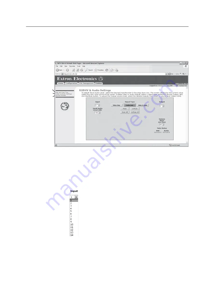
The RGB and Audio Settings page provides a way to set the input audio gain and 
attenuation, set the output volume, and mute and unmute all video and audio 
outputs.  Access the RGB and Audio Settings page (fi gure 6-10) by clicking the 
RGB & Audio Settings link on the Control page.

Global Presets

Refresh

Set & View Ties

Figure 6-10 — RGB and Audio Settings page

Change the input gain and attenuation (audio models only)

Users can set each input’s level of audio gain or attenuation (-18 dB to +24 dB) from 
the RGB and Audio Settings page.  Audio levels can be adjusted so there are no 
noticeable volume differences between sources.

Change an input’s audio level setting as follows:

1. 

Click the Input drop box.  A drop down scroll box appears (fi gure 6-11).


Figure 6-11 — Input selection drop box

im Vertrieb von

            CAMBOARD Electronics

www.camboard.de

Tel. 07131 911201
Fax 07131 911203

[email protected]

Summary of Contents for MPX 866 A

Page 1: ...MPX 866 A Media Presentation Matrix Switcher 68 1270 01 Rev B 09 06 im Vertrieb von CAMBOARD Electronics www camboard de Tel 07131 911201 Fax 07131 911203 ce info camboard de ...

Page 2: ...anleitungen genau durchlesen und verstehen Au ewahren der Anleitungen Die Hinweise zur elektrischen Sicherheit des Produktes sollten Sie au ewahren damit Sie im Bedarfsfall darauf zurückgreifen können Befolgen der Warnhinweise Befolgen Sie alle Warnhinweise und Anleitungen auf dem Gerät oder in der Benutzerdokumentation Keine Zusatzgeräte Verwenden Sie keine Werkzeuge oder Zusatzgeräte die nicht a...

Page 3: ...Matrix Switcher Unbalanced Input Balanced Input high impedance high impedance Do not tin the wires Ring Sleeve s 0 3 7 mm max Tip Sleeve Tip Sleeve Tip Ring Tip Ring c Connect up to 6 balanced or unbalanced stereo audio or mono audio devices to the 5 pin captive screw connectors in the computer audio output subgroup Step 4 RS 232 If desired connect control systems and or PCs to the rear panel RS 2...

Page 4: ...ct an input format Inputs 11 through 14 are configurable as either composite video or S video as follows 1 Press and release the Esc button 2 Press and hold the Video button until the Video LED starts to blink Release the button 3 Select the input to configure by pressing and releasing one of the Input 11 through Input 14 buttons Either the Output 7 LED or the Output 8 LED lights to indicate selec...

Page 5: ...nel Configuration Port 2 10 Chapter Three Operation 3 1 Front Panel Controls and Indicators 3 2 Definitions 3 2 Computer video input and output buttons and LEDs 3 2 Video input and output buttons and LEDs 3 3 Input and output label panels 3 3 Control buttons and LEDs 3 4 I O controls 3 6 Front Panel Operations 3 7 Power 3 7 Creating a configuration 3 8 Example 1 Creating a set of computer video an...

Page 6: ... 37 Rear Panel Controls 3 38 Performing soft system resets 3 38 Performing a hard reset 3 40 Optimizing the Audio 3 41 Troubleshooting 3 41 General checks 3 41 Configuration Worksheets 3 42 Worksheet example 1 System equipment 3 42 Worksheet example 2 Daily configuration 3 43 Worksheet example 3 Test configuration 3 44 Blank configuration worksheet 3 45 Chapter Four SIS Programming and Control 4 1...

Page 7: ...7 Use DHCP checkbox 5 7 Date field 5 8 Time local field 5 8 Sync Time to PC button 5 8 GMT offset field 5 8 Use Daylight Savings checkbox 5 8 Administrator Password field 5 9 User Password field 5 9 Update firmware 5 10 Upload HTML files 5 11 Windows buttons drop boxes and trash 5 12 Windows menus 5 12 File menu 5 12 Tools menu 5 13 Audio Input Configuration Selection 5 15 Preferences menu 5 15 Ma...

Page 8: ...Address field 6 5 Date Time Settings fields 6 6 Video Input Settings Page 6 6 Passwords Page 6 7 Firmware Upgrade Page 6 8 File Management Page 6 9 Set and View Ties Page 6 10 Create a tie 6 11 RGB and Audio Settings page 6 12 Change the input gain and attenuation audio models only 6 12 Mute and unmute one or all outputs 6 14 Change the output volume level 6 15 Global Presets page 6 17 Save a pres...

Page 9: ...age return line feed A 5 Close A 5 Help A 5 Quit A 5 Subnetting A Primer A 6 Gateways A 6 Local and remote devices A 6 IP addresses and octets A 6 Subnet masks and octets A 6 Determining whether devices are on the same subnet A 7 Appendix B Reference Information B 1 Specifications B 2 Part Numbers and Accessories B 6 MPX 866 A part numbers B 6 Optional accessories B 6 Cables B 7 Bulk cable and ter...

Page 10: ...trix Switcher Table of Contents vi PRELIMINARY 68 1270 01 B 09 06 All trademarks mentioned in this manual are the properties of their respective owners im Vertrieb von CAMBOARD Electronics www camboard de Tel 07131 911201 Fax 07131 911203 ce info camboard de ...

Page 11: ...tion Matrix Switcher 1 Chapter One Introduction About this Manual About the Media Presentation Matrix Switcher Definitions Features im Vertrieb von CAMBOARD Electronics www camboard de Tel 07131 911201 Fax 07131 911203 ce info camboard de ...

Page 12: ...and low resolution video outputs subgroup A 14 input by 6 output primary audio matrix switcher N Video ties can only be made within the same group Audio ties can only be made to outputs in the computer audio subgroup outputs 1 through 6 CO MP UT ER IN VID EO OU T 7 9 11 8 10 12 9 11 13 10 12 14 PAS S THR OUG H S V IDE O VID EO Y C Y V ID C VID EO IN AU DIO INP UT S CO MP UT ER OU T Y V ID C Y V ID...

Page 13: ...ties can only be made to the computer audio subgroup Adjustable input audio gain and attenuation compensates for level differences between audio inputs The switcher has two primary and secondary RS 232 ports and a local area network LAN Ethernet port for remote control and reporting The matrix switcher is programmed with Extron s Simple Instruction Set SIS a set of basic ASCII code commands that p...

Page 14: ... NTSC 4 43 PAL or SECAM S video and or composite video on BNC connectors Inputs 9 and 10 the first two low resolution video group video inputs are composite video only Input 9 is a genlock reference All other low resolution inputs are synced to input 9 Inputs 11 through 14 the remaining low resolution video group video inputs can accept either S video or composite video Outputs 7 and 8 the first t...

Page 15: ...esets and adjustment of audio levels can be performed on the front panel or via the Ethernet or RS 232 link The Ethernet and RS 232 links allow remote control via a PC or control system The Ethernet link allows multiple remote links with two levels of password protection Front panel control The front panel controller supports input and output selection preset creation and selection and audio gain ...

Page 16: ...nce You can then recall those configurations when needed with a few simple steps Rack mounting Rack mountable in any conventional 19 wide rack Front panel security lockout Executive mode If a switcher is installed in an open area where operation by unauthorized personnel may be a problem a security lockout feature can be implemented When the front panel is locked a special button combination or SI...

Page 17: ...Presentation Matrix Switcher 2 Chapter Two Installation Mounting the Switcher Connection and Configuration Front Panel Port im Vertrieb von CAMBOARD Electronics www camboard de Tel 07131 911201 Fax 07131 911203 ce info camboard de ...

Page 18: ...ot compromised 3 Mechanical loading Mounting of the equipment in the rack should be such that a hazardous condition is not achieved due to uneven mechanical loading 4 Circuit overloading Consideration should be given to the connection of the equipment to the supply circuit and the effect that overloading of the circuits might have on overcurrent protection and supply wiring Appropriate considerati...

Page 19: ...MPX 866 A Media Presentation Matrix Switcher Video input and output N The switcher does not alter the computer video inputs in any way The signal output is in the same format as the input The switcher can connect to up to as many as eight computer video sources and output to as many as six video devices Computer video group a RGB video inputs Connect the analog computer video sources to the Comput...

Page 20: ...ation to change the setting e Composite video outputs Video Output 7 and Video Output 8 Connect composite video displays to these female BNC connectors N If the input tied Video Output 7 or Video Output 8 is S video the switcher encodes the input to composite video If the tied input is composite video the switcher passes it through to the output with no processing f S video outputs Video Output 9 ...

Page 21: ...udio inputs C The captive screw audio connector can easily be inadvertently plugged partially into one receptacle and partially into an adjacent receptacle This misconnection could damage the audio circuits Ensure that the connector is plugged fully and only into the desired input or output N The length of exposed wires is critical The ideal length is 0 3 7 mm If the stripped section of wire is lo...

Page 22: ...tive terminal will damage the audio output circuits N The length of exposed wires is critical The ideal length is 0 3 7 mm If the stripped section of wire is longer than 0 3 the exposed wires may touch causing a short circuit between them If the stripped section of wire is shorter than 0 3 wires can be easily pulled out even if tightly fastened by the captive screws The volume level for each outpu...

Page 23: ...ional Figure 2 5 RS 232 connector N The length of exposed wires is critical The ideal length is 0 3 7 mm If the stripped section of wire is longer than 0 3 the exposed wires may touch causing a short circuit between them If the stripped section of wire is shorter than 0 3 wires can be easily pulled out even if tightly fastened by the captive screws N These two ports are hardwired for RS 232 only i...

Page 24: ...that has downloaded HTML pages from the switcher Ethernet connection indicators The Link and Act LEDs indicate the status of the Ethernet connection The Link LED indicates that the switcher is properly connected to an Ethernet LAN This LED should light steadily The Act LED indicates transmission of data packets on the RJ 45 connector This LED should flicker as the switcher communicates Cabling and...

Page 25: ... and hold the button while the switcher is running or while you power up the switcher for different reset levels See Performing soft system resets in chapter 3 Operation for details Events mode 3 reset Hold Reset for 3 seconds then release and push again to toggle events monitoring on and off IP settings mode 4 reset Hold Reset for 6 seconds then release and push again to reset the switcher s IP f...

Page 26: ...lels the rear panel RS 232 Secondary port If a front panel configuration connection is made the rear panel RS 232 Secondary port becomes inactive and the front panel Configuration port is active This port is RS 232 only with its default protocols as follows 9600 baud no parity 8 data bits 1 stop bit no flow control N The Configuration port can operate at 9600 19200 38400 or 115200 baud rates See C...

Page 27: ...er Three Operation Front Panel Controls and Indicators Front Panel Operations Rear Panel Controls Optimizing the Audio Troubleshooting Configuration Worksheets im Vertrieb von CAMBOARD Electronics www camboard de Tel 07131 911201 Fax 07131 911203 ce info camboard de ...

Page 28: ...ry presets can be stored in memory Preset locations are assigned to the input buttons and where necessary output buttons Up to 26 presets can be selected from the front panel for either saving or retrieving When a preset is retrieved from memory it becomes the current configuration Preset numbers larger than 26 are accessible under RS 232 and Ethernet control Computer video input and output button...

Page 29: ...the selected video format composite Output 7 or S video Output 8 for configurable inputs 11 through 14 See Selecting composite video or S video on page 3 26 Display the audio level of the selected input See Viewing and adjusting the input audio level on page 3 28 Input and output label panels e Input and output label panels These translucent panels can be removed and replaced to insert labels behi...

Page 30: ...tential tie has been created but not saved Indicate that a global preset has been selected to be saved or recalled but that the preset action has not been accomplished With the Preset View and Esc buttons select Serial Port Configuration mode See Selecting the RS 232 Primary port s baud rate on page 3 37 Select 9600 baud for the RS 232 Primary port in Serial Port Configuration mode See Selecting t...

Page 31: ...ing the RS 232 Primary port s baud rate on page 3 37 i Esc button and LED The Esc button and LED have two primary functions and five secondary functions Cancel operations or selections in progress and reset the front panel button indicators N The Esc button does not reset the current configuration the Video button and Audio button selection any presets or any audio gain or attenuation or volume se...

Page 32: ...ode on page 3 36 With the Audio button commands the front panel system reset See Performing a system reset from the front panel on page 3 36 k Audio button and LED The Audio button and LED have two primary functions and three secondary functions Selects and deselects audio for a configuration that is being created or viewed The LED lights to indicate that audio is available for configuration or vi...

Page 33: ...wer by connecting the power cord to an AC source The switcher performs a self test that flashes the front panel LEDs on and off An error free power up self test sequence leaves all I O and control LEDs unlit The lit unlit status of the Video LED and the Audio LED is the same as when the switcher was powered off The current configuration and all presets are saved in non volatile memory When power i...

Page 34: ... between the low resolution video input subgroup and the low resolution video output subgroup are always made with the audio broken away In such an operation the switcher automatically ties the audio to an output in the computer video audio outputs subgroup outputs 1 through 6 as follows If the video is tied to output 7 the audio is tied to output 1 If the video is tied to output 8 the audio is ti...

Page 35: ... current configuration 1 Press and release the Esc button figure 3 3 CONTROL ENTER PRESET VIEW ESC Press the Esc button to clear all selections The LED blinks once Blink once 1 1 Figure 3 3 Clear all selections 2 To select video and audio for the tie if necessary press and release the Video button and the Audio button until the LEDs light figure 3 4 VIDEO AUDIO I O Press the Video button to toggle...

Page 36: ...ll be tied to these outputs The Enter LED blinks to indicate the need to confirm the change Blinking LED Figure 3 6 Select the outputs 5 Press and release the Enter button figure 3 7 ENTER The Enter LED and all input LEDs and output LEDs return to the unlit state Press the Enter button to confirm the configuration change Figure 3 7 Press the Enter button The current configuration figure 3 8 is now...

Page 37: ...To select video only for the tie if necessary press and release the Video button and the Audio button figure 3 10 VIDEO AUDIO I O Press the Video button to toggle on and off The LED lights when selected Press the Audio button to toggle on and off The LED is unlit when deselected Figure 3 10 Select video only 3 Press and release the input 5 button figure 3 11 2 3 4 5 6 7 COMPUTER INPUTS 1 2 3 4 5 6...

Page 38: ...nd release the Enter button figure 3 13 ENTER The Enter LED and all input LEDs and output LEDs return to the unlit state Press the Enter button to confirm the configuration change Figure 3 13 Press the Enter button The current configuration figure 3 14 is now Input 5 video tied to output 1 output 3 output 4 and output 6 Input 5 audio tied to output 3 output 4 and output 6 Input 5 video tied to out...

Page 39: ...ecessary press and release the Video button and the Audio button figure 3 16 VIDEO AUDIO I O Press the Video button to toggle on and off The LED is unlit when deselected Press the Audio button to toggle on and off The LED lights when selected Figure 3 16 Select audio only 3 Press and release the input 5 button figure 3 17 2 3 4 5 6 7 COMPUTER INPUTS 1 2 3 4 5 6 COMPUTER AUDIO OUTPUTS Press and rel...

Page 40: ...e Enter button figure 3 19 ENTER The Enter LED and all input LEDs and output LEDs return to the unlit state Press the Enter button to confirm the configuration change Figure 3 19 Press the Enter button The current configuration figure 3 20 is now Video Input 5 video tied to output 1 output 3 output 4 and output 6 Audio Input 5 audio tied to output 3 and output 6 Input 5 video tied to outputs 1 3 4...

Page 41: ...dio is tied to output 2 If the video is tied to output 9 the audio is tied to output 3 If the video is tied to output 10 the audio is tied to output 4 If the video is tied to output 11 the audio is tied to output 5 If the video is tied to output 12 the audio is tied to output 6 1 Press and release the Esc button figure 3 21 CONTROL ENTER PRESET VIEW ESC Press the Esc button to clear all selections...

Page 42: ...n video input will be tied to these outputs The Computer Audio Output 1 and Output 2 buttons blink to indicate that the selected audio input will be tied to these outputs The Audio button blinks to indicate that audio is broken away The Video button remains lit The Enter LED blinks to indic the need to confirm the chan Blinking LED Figure 3 24 Select the outputs 5 Press and release the Enter butto...

Page 43: ...LEDs that are lit 2 Press and release the View button All of the LEDs for outputs that are not tied light 3 Select video audio or both to view by pressing the Video button and or the Audio button 4 Select the desired input or output s whose ties you wish to view by pressing the input and output buttons N When you enter View only mode the output LEDs light for all outputs without ties Likewise when...

Page 44: ...nce 1 1 Figure 3 27 Clear all selections 2 Press and release the View button to enter View Only mode The View button lights red 3 To select both video and audio for viewing if necessary press and release the Video button and the Audio button figure 3 28 VIDEO AUDIO I O 1 2 3 4 5 6 COMPUTER AUDIO OUTPUTS Until you select an input the buttons for all untied outputs light Press the Audio button to to...

Page 45: ...t buttons for audio outputs that are not tied to input 5 are unlit The output buttons for outputs that are tied to input 5 light to indicate audio ties audio breakaway The Audio LED remains lit to indicate that only audio is selected Press the Video button to delesect it The LED is unlit when deselected Figure 3 30 Deselect video to view audio ties only 6 Press and release the Video button and the...

Page 46: ...s blink to indicate the mute or return to their previous state to indicate the unmute 5 Press and release the View button to return to normal switcher operation N You can mute video only or audio only outputs only in a single operation Video and audio can both can be muted but in separate operations one and then the other Pressing and releasing the Video button and the Audio button toggles each se...

Page 47: ... or audio for viewing and muting if necessary press and release the Video button and the Audio button until one or the other is lit figure 3 34 N This example shows the front panel indications if example 1 example 2 and example 3 have been completed VIDEO AUDIO I O 1 2 3 4 5 6 COMPUTER AUDIO OUTPUTS Until you select an input the buttons for all untied outputs light Press the Audio button to toggle...

Page 48: ... Computer Output 4 button 2 seconds Blinking LED Figure 3 35 Mute the outputs 5 One at a time press and hold the Computer Audio Output 3 and then the Computer Audio Output 4 buttons figure 3 36 for approximately 2 seconds until the buttons lights steadily The output 3 and output 4 video and audio signals are unmuted COMPUTER AUDIO OUTPUTS COMPUTER AUDIO OUTPUTS 2 3 4 5 2 3 4 5 The LEDs stop blinki...

Page 49: ...is recalled The video format composite or S video for outputs 11 through 14 are not saved and they do not change when a preset is recalled Presets cannot be viewed from the front panel unless recalled as the current configuration Presets can be viewed using Extron s Windows based control program See Chapter 5 Matrix Software for more details The current configuration and all presets are stored in ...

Page 50: ...OL ENTER PRESET VIEW COMPUTER AUDIO OU The Enter LED blinks to indicate the need to save the preset The Preset LED continues to blink Press and release the Computer Output 1 button The LED blinks to indicate that this preset number is selected but not saved Blinking LED Figure 3 40 Select the preset 4 Press and release the Enter button figure 3 41 The current configuration is now stored in the sel...

Page 51: ...15 Preset 16 Preset 18 Preset 17 CONTROL ENTER PRESET VIEW COMPUTER AUDIO OU The Enter LED blinks to indicate the need to save the preset The Preset LED remains lit Press and release the Computer Output 1 button The LED blinks to indicate that this preset number is selected but not recalled Blinking LED Figure 3 44 Select the preset 4 Press and release the Enter button figure 3 45 The configuratio...

Page 52: ...sing the Enter or Preset button also exits Video mode Pressing the Preset button changes to Recall Preset mode For the switcher to recognize the change and create a new configuration map you must create a new tie for the input whose format was changed Exiting Video mode by pressing the Video button always returns the I O configuration to video and audio selected for configuration Example 9 Selecti...

Page 53: ...release the Video Output button to change the video format as follows 7 Composite 8 S video In this example the input is set to S video Figure 3 49 Video format selection N If desired select another of configurable video inputs 11 through 14 to view or change the video format for that input 5 Press and release the Video button to exit the Video mode figure 3 50 AUDIO VIDEO I O The Video LED stops ...

Page 54: ... 2 To enter Audio mode press and hold the Audio button until the Audio LED begins to blink then release the button 3 Press and release an input button to select an input The output LEDs display the audio level for the selected input Each output LED indicates 1 dB of gain or attenuation when blinking and another 1 dB when lit steadily The Esc and View LEDs display the polarity gain or attenuation S...

Page 55: ... F S F S F S F S S F F S View Esc 18 17 16 15 14 13 12 11 10 24 23 22 21 20 19 6 5 4 3 2 1 8 7 6 5 4 3 2 1 F S F S F S F S F 16 17 18 dB 9 8 10 12 14 16 18 20 22 7 6 5 4 3 2 1 0 1 2 3 4 5 6 7 8 9 10 11 12 13 14 15 17 15 13 11 24 23 21 19 16 17 18 S F on blinking fast blinking slowly off im Vertrieb von CAMBOARD Electronics www camboard de Tel 07131 911201 Fax 07131 911203 ce info camboard de ...

Page 56: ...ss and hold the Audio button for approximately 2 seconds figure 3 53 AUDIO VIDEO I O AUDIO The LED blinks to indicate Audio mode Release the button Press and hold the Audio button 2 seconds Blinking LED Figure 3 53 Select Audio mode 3 Press and release the input 5 button figure 3 54 1 2 3 4 5 6 1 2 3 4 5 6 COMPUTER INPUTS VIEW ESC 7 8 9 VIDEO O COMPUTER AUDIO OUTPUTS Press and release the Computer...

Page 57: ...DIO OUTPUTS In this example the output buttons and View and Esc buttons display an audio gain level of 1 dB The output LEDs independent of video group display the selected input s audio level The View and Esc LEDs display the polarity gain or attenuation Press the View button to decrease the input audio level by 1dB per button push Lit LED Unlit LED S S Blinking slowly Figure 3 55 Adjust the input...

Page 58: ...or configuration Pressing the Enter or Preset button also exits Audio mode Pressing the Preset button changes to Recall Preset mode Reading the displayed volume N This section is a detailed look at reading the displayed output volume display If you do not need to read the exact value of the volume setting skip this section There are 65 steps of volume attenuation with 1 dB per step button push exc...

Page 59: ...essive steps of volume increase cause consecutive LEDs to blink slowly blink quickly and then light steadily At full volume no attenuation is applied to the output and all input LEDs are lit steadily See the table at right to read the volume display 8 7 Input LED dB of attenuation S F 98 6 5 4 3 2 1 8 7 6 5 4 3 2 1 59 Output volume 0 5 5 7 63 62 8 5 10 61 60 11 5 13 14 5 58 57 16 17 5 19 56 55 54 ...

Page 60: ... figure 3 58 AUDIO VIDEO I O AUDIO The LED blinks to indicate Audio mode Release the button Press and hold the Audio button 2 seconds Blinking LED Figure 3 58 Select Audio mode 3 Press and release the output 1 button figure 3 59 13 14 12 PUTS 1 2 C COMPUTER INPUTS 1 7 8 2 3 4 5 6 Press and release the Computer Output 1 button The LED lights The input LEDs independent of video group display the sel...

Page 61: ...splay the selected output s audio volume level In this example the lit input buttons indicate 56 5 to 62 5 percent of the applied audio input The unlit input buttons indicate an audio volume attenuation of 25 dB to 29 dB 26 dB attenuation 61 volume Press the Esc button to decrease the audio attenuation thereby increasing the audio level that is applied to the output volume level by 1 dB per button...

Page 62: ...buttons Blink twice 2 2 2 Figure 3 62 Toggle front panel lock on or off Performing a system reset from the front panel The front panel reset is identical to the EZXXX SIS command see chapter 4 SIS Programming and Control A system reset Clears all ties and presets Clears all video and audio mutes Sets all input audio levels to unity gain 0 dB Sets all output volume levels to 100 0 dB of attenuation...

Page 63: ...nter Preset View and Esc figure 3 64 CONTROL ENTER PRESET VIEW ESC CONTROL ENTER PRESET VIEW ESC All Control LEDs light with one flashing The flashing Control LED indicates the baud rate as follows Enter 9600 Preset 19200 View 38400 Esc 115200 Press and hold the Enter Preset View and Esc buttons Lit LED Blinking LED Figure 3 64 Baud rate display 2 Release the Control buttons 3 To change a value pr...

Page 64: ...cher settings to their default settings Events mode 3 reset This function toggles the monitoring of events on or off if events monitoring was on this function turns it off if it was off it is turned on IP settings mode 4 reset The IP settings reset performs the following functions Enables Arp program capability Resets the IP address to the factory default 192 168 254 254 Resets the subnet mask to ...

Page 65: ...e times 3 1 3 IP Settings Reset Press and hold the Reset button Release then immediately press and hold 6 seconds Reset LED flashes twice Release the Reset button Reset LED flashes three times 3 2 3 Absolute Reset Press and hold the Reset button Release then immediately press and hold 9 seconds Reset LED flashes three times Release the Reset button Reset LED flashes three times 3 3 3 Figure 3 67 W...

Page 66: ...nd on unless a firmware update is performed before the power cycle 1 If necessary turn off power to the switcher 2 Press and hold the Reset button on the rear panel while you apply AC power to the switcher figure 3 68 Power RESET LAN CT LINK RESET LAN CT LINK Press and hold the Reset button while you apply power to the switcher The switcher flashes the front panel LEDs and then turns them off Cont...

Page 67: ...pment such as a VU meter 4 As necessary adjust the input audio level of each input see Viewing and adjusting the input audio level in this chapter so that the approximate output level is the same for all selected inputs 5 As necessary adjust the output audio level of each input see Viewing and adjusting the output volume in this chapter Troubleshooting This section gives recommendations on what to...

Page 68: ...he Extron VTG 450 video test generator connected to input 8 or to input 13 enables a video test pattern to be sent to one several or all output devices within the video group for problem isolation or adjustment purposes An audio test tape or CD could be used in a similar manner to check out the audio components connected to the computer video audio subgroup 1 2 3 4 5 6 7 8 1 2 3 4 5 6 Computer vid...

Page 69: ...crowd in the conference room computer video output 4 Tied through a scaler to a VCR computer video output 6 for recording The audio from her microphone input 9 is Played in the hall output 5 Sent to the VCR output 6 Classical music from the CD player input 14 is played in the lobby output 3 1 2 3 4 5 6 7 8 1 2 3 4 5 6 Preset Title Video Audio Fill in the preset number and use colors or dashes etc ...

Page 70: ...Video Audio Fill in the preset number and use colors or dashes etc to make connecting lines Indicate if the configuration is for video audio or both 9 10 11 13 14 7 8 9 10 12 11 12 PC 1 RGB 201 16 System tune up PC 2 RGB 201 ISS 408 Wallbox 1 Wallbox 2 VTG 450 Camera mic podium Classrm VCR 1 Classrm DVD 1 Document camera VTG 450 Audio CD Main hall PJ 1 Main hall PJ 3 Lobby sound Conf room Sound sy...

Page 71: ...connecting lines Indicate if the configuration is for video audio or both 9 10 11 13 14 7 8 9 10 12 11 12 Computer video and or audio subgroup input sources Computer video audio subgroup output destinations Low resolution video and or audio subgroup input sources Low resolution video subgroup output destinations im Vertrieb von CAMBOARD Electronics www camboard de Tel 07131 911201 Fax 07131 911203...

Page 72: ...Operation cont d MPX 866 A Media Presentation Matrix Switcher Operation 3 46 PRELIMINARY im Vertrieb von CAMBOARD Electronics www camboard de Tel 07131 911201 Fax 07131 911203 ce info camboard de ...

Page 73: ...ing and Control RS 232 Links Ethernet Link Host to Switcher Instructions Switcher Initiated Messages Switcher Error Responses Using the Command Response Tables Special Characters im Vertrieb von CAMBOARD Electronics www camboard de Tel 07131 911201 Fax 07131 911203 ce info camboard de ...

Page 74: ...an be configured to operate at the 9600 19200 38400 or 115200 baud rate N These three ports are hardwired for RS 232 only The rear panel RS 232 Secondary port is active only if the front panel Configuration port is not in use If a front panel configuration connection is made the rear panel RS 232 Secondary port becomes inactive and the front panel Configuration port is active N The switcher can op...

Page 75: ...ear panel RS 232 Secondary port If a front panel configuration connection is made the rear panel RS 232 Secondary port becomes inactive and the front panel Configuration port is active The optional 9 pin D to 2 5 mm mini jack TRS RS 232 cable part 70 335 01 figure 4 2 can be used for connection to the Configuration port 6 feet 1 8 m Part 70 335 01 5 1 9 6 Sleeve Gnd Ring Tip 9 pin D Connection TRS...

Page 76: ...ge 2 Orange 3 White green 3 White green 4 Blue 4 Blue 5 White blue 5 White blue 6 Green 6 Green 7 White brown 7 White brown 8 Brown 8 Brown Crossover cable Side 1 Side 2 Pin Wire color Pin Wire color 1 White orange 1 White green 2 Orange 2 Green 3 White green 3 White orange 4 Blue 4 Blue 5 White blue 5 White blue 6 Green 6 Orange 7 White brown 7 White brown 8 Brown 8 Brown Figure 4 3 RJ 45 Etherne...

Page 77: ...message when the controlling system is connected using TCP IP or Telnet and the switcher is password protected This message means that the switcher requires an administrator or user level password before it will perform the commands entered via this link The switcher repeats the password message response for every entry other than a valid password until a valid password is entered Login Administra...

Page 78: ...s the command and sends a response to the host device If the switcher is unable to perform the command because the command is invalid or contains invalid parameters the switcher returns an error response to the host The error response codes are E01 Invalid input channel number too large E10 Invalid command E11 Invalid preset number E12 Invalid output number too large E13 Invalid value out of range...

Page 79: ...eps of gain or attenuation X Audio gain 0 24 1 dB step X Audio attenuation 1 18 1 dB step X Volume adjustment range 0 64 1 dB step except for 0 to 1 which is 34 5 dB see the table on page 4 11 X Mute executive mode power supply 0 off not OK 1 on OK X1 Global preset 32 maximum 0 current configuration X1 Video audio mute 0 no mutes 1 video mute 2 audio mute 3 video and audio mute X1 Signal detection...

Page 80: ...esponse is OutX InX All when the video and audio ties are made between the computer video input group and the computer audio output group because audio always follows the video The response is Qik when video and audio ties are made between the low resolution video input group and the low resolution video output group because audio is automatically broken away to the computer audio group Example co...

Page 81: ...video group outputs N The tie all command for RGB and the tie all command for video can be used interchangeably on the switcher for ties within the same group Tie input to all outputs audio only X InX Aud Audio breakaway Read ties Read RGB output tie X X RGBHV input X tied to output X Read video output tie X X Video input X tied to output X N The read tie command for RGB and the read tie command f...

Page 82: ...ent audio input 6 level from 2 dB to 3 dB Decrement level X G InX AudX Decrease audio level by 1 dB Example 7 G In07 Aud 09 Decrement audio input 7 level from 08 dB to 9 dB Read input gain X G X Audio output volume N The table on the next page defines the value of each audio volume step Set audio volume to a specific value X X V OutX VolX Example 1 50v Out01 Vol50 Set output 1 volume to 79 Increme...

Page 83: ...6 49 50 5 53 5 52 55 56 5 59 5 58 61 25 23 24 22 21 20 62 5 65 5 64 67 68 5 70 dB of attenuation Output volume 19 17 18 16 15 13 14 12 11 9 10 8 7 5 6 4 71 5 74 5 73 76 77 5 80 5 79 82 83 5 86 5 85 88 89 5 92 5 91 94 3 1 2 0 95 5 98 5 97 100 01 02 03 04 05 06 07 08 09 10 11 12 13 14 15 16 17 18 19 20 45 46 47 48 49 50 51 52 53 54 55 56 57 58 59 60 61 62 63 64 21 22 23 24 25 26 27 28 29 30 31 32 33...

Page 84: ... of the specified preset can unexpectedly become part of the newly created preset Clear a global preset E X1 P0 SprX1 Clear all ties in preset X1 Directly write a global preset E X1 PX X X X X X X X Enter as many ties as are valid for this model The tie all tie RGBHV tie video and tie audio commands are all valid SprX1 Example E 27P0 Spr27 E 27P2 5 10 2 13 11 3 6 Brackets are shown to separate tie...

Page 85: ... the IP address to 192 168 254 254 and the subnet mask to 255 255 0 0 View ties gain volume mutes video format and presets View RGBHV output tie X X Example 5 07 Input 7 computer video tied to output 5 View video output tie X X Example 7 12 Input 12 low resolution video tied to output 7 View audio output tie X X Example 3 06 Input 6 audio tied to output 3 View input gain X G X Example 4G 02 Gain f...

Page 86: ...t 10 to outputs 10 through 12 No input is tied to outputs 6 and 8 N If you enter EX1 1 1VC where X1 0 the switcher returns its current video configuration View audio global preset configuration EX1 1 2VC X 1 X 2 X 3 X 16 Aud Show preset X1 s audio configuration Show the audio input tied to 6 sequential outputs starting from output 1 Audio outputs 7 through 16 are not present on this switcher model...

Page 87: ...8 825 01 N There are up to three separate sets of Extron firmware that the switcher can report on the MPX controller firmware which is the overall control firmware the Ethernet protocol firmware which handles the Ethernet interface and the latest optional Extron firmware update which is available at www Extron com Query controller firmware version Q X1 Example Q 1 23 The factory installed MPX cont...

Page 88: ...ion Information requests continued Request system status S X1 X1 X1 X1 X1 X1 Response description S 3 3V 5V 5V 2 5V 15V 15V Temp Example S 3 29 5 04 5 14 15 27 15 15 120 20 15V power system at 15 15V Temperature 120 20 degrees 3 3V power system at 3 29V Command response table for SIS commands continued im Vertrieb von CAMBOARD Electronics www camboard de Tel 07131 911201 Fax 07131 911203 ce info c...

Page 89: ... Number of open connections 0 255 X3 Password 12 alphanumeric characters N The following characters are invalid in passwords space and X3 DHCP 0 off 1 on X3 Port 01 rear panel RS 232 Primary port 02 rear panel RS 232 Secondary port front panel Cofiguration port N The rear panel RS 232 Secondary port X3 02 is active only if the front panel Configuration port is not in use If a front panel configura...

Page 90: ...address EX2 CI IpiX2 Read IP address ECI X2 Read hardware address ECH X2 Read of open connections ECC X3 Set subnet mask EX2 CS IpsX2 Read subnet mask ECS X2 Set gateway IP address EX2 CG IpgX2 Read gateway IP address ECG X2 Set administrator password EX3 CA Ipa X3 Read administrator password ECA X3 Reset clear administrator password E CA Ipa X3 Set user password EX3 CU Ipu X3 Read user password E...

Page 91: ... for specific functions The switcher will not accept these characters as part of preset names the switcher s name passwords or locally created file names The switcher rejects the following characters space spaces are ok for names semicolon colon and im Vertrieb von CAMBOARD Electronics www camboard de Tel 07131 911201 Fax 07131 911203 ce info camboard de ...

Page 92: ... and Control cont d MPX 866 A Media Presentation Matrix Switcher SIS Programming and Control 4 20 PRELIMINARY im Vertrieb von CAMBOARD Electronics www camboard de Tel 07131 911201 Fax 07131 911203 ce info camboard de ...

Page 93: ...tation Matrix Switcher 5 Chapter Five Matrix Software Matrix Switchers Control Program Special Characters Button Label Generator im Vertrieb von CAMBOARD Electronics www camboard de Tel 07131 911201 Fax 07131 911203 ce info camboard de ...

Page 94: ...lectronics N The program was designed to control most Extron matrix switchers but its operation is limited to the features and configuration of your MPX switcher N The MPX switcher can support either the front panel I O Configuration port or the rear panel Remote RS 232 ports The program can operate at 9600 19200 38400 or 115200 baud rates for either port See Selecting the RS 232 Primary port s ba...

Page 95: ...e the control program itself 1 To run the Matrix Switcher Control Program select Start Programs Extron Electronics Matrix Switchers MATRIX Switcher Control Pgm The Comm Port Selection window figure 5 1 appears Figure 5 1 Comm port selection window 2 Choose either the comm port that is connected to the matrix switcher s RS 232 ports IP LAN or Emulate If you selected a comm port check the baud rate ...

Page 96: ...s entered the program beeps and returns to the password entry display 4 The Extron Matrix Switcher Control Program window figure 5 3 and figure 5 4 appears The window displays the current configuration of the attached matrix To set up audio in follow mode audio and video have the same tie configuration select the Follow box at the bottom of the window To set up audio in breakaway mode audio and vi...

Page 97: ...tcher Matrix Software PRELIMINARY Figure 5 3 Extron Matrix Switcher Control Program window blank Figure 5 4 Sample program window complete im Vertrieb von CAMBOARD Electronics www camboard de Tel 07131 911201 Fax 07131 911203 ce info camboard de ...

Page 98: ...g the current password Matrix IP Address field The Matrix IP Address field contains the IP address of the connected matrix switcher This value is encoded in the flash memory in the switcher Valid IP addresses consist of four 1 2 or 3 digit numeric subfields separated by dots periods Each field can be numbered from 000 through 255 Leading zeroes up to 3 digits total per field are optional Values of...

Page 99: ...phic cursor becomes a text cursor 2 Edit the address as desired 3 Press the Tab key on the keyboard or click in another field to exit the Gateway IP Address field 4 Click the Take button to make the address change take affect Subnet Mask field The Subnet Mask field is used to determine whether the matrix switcher is on the same subnet as the controlling PC when you are subnetting For more informat...

Page 100: ... to exit the set time field 4 Click the Take button to make the time change take affect Sync Time to PC button Clicking the mouse on the Sync Time to PC button causes the computer you are operating to send its internal time to the switcher in a set time command GMT offset field The GMT field displays the amount of time in hours and minutes that the local time varies from the GMT international time...

Page 101: ... cursor 2 Edit the case sensitive password as desired 3 Press the Tab key on the keyboard or click in another field to exit the Administrator Password field 4 Click the Take button to make the password change take affect User Password field The User Password field displays the password required to log on to the matrix switcher via the Ethernet port as a user without all of the administrator s righ...

Page 102: ...b site www extron com select the CrossPoint MAV Plus product category and select the latest firmware install package exe file for download Note the folder to which you save the firmware file 2 Run the executable exe file to decompress the firmware file 3 Start the Matrix Switcher Control Program and connect to the matrix switcher See Using the software in this chapter steps 1 through 4 starting on...

Page 103: ...s List window figure 5 7 provides a way to view the contents of the switcher s file system and upload custom HTML pages to the switcher Figure 5 7 HTML Files List window Upload HTML pages as follows N The files listed in figure 5 7 are shown for example only and may not be present on your switcher N The HTML Files List window is for inserting your own HTML pages This is not the window to replace t...

Page 104: ... Activates the selected preset as the current configuration Save as Allows the current set of ties to be saved as a preset Enter the preset number when prompted to do so Delete Allows the current preset to be deleted Changes Take Allows you to save to file any changes made to the displayed configuration Changes Cancel Returns to the previous screen undoing any changes you have made Trash can Drag ...

Page 105: ...audio adjustment Figure 5 8 Audio gain window Audio Output volume settings Displays the audio output level setting for a single input or for all inputs and allows you to change it figure 5 9 The level is expressed as a percentage of the input audio volume that is applied to the output 0 is full attenuation audio is silent 100 is full volume Figure 5 9 Mute and Output Volume window Mute output sett...

Page 106: ... page 5 6 HTML file manager Displays a list of HTML files installed on the switcher and allows you to upload custom files from a connected PC to the switcher See Upload HTML files on page 5 11 Hardware status Provides an overall view of the status of the matrix switcher including the power supply status and the individual voltages the operating temperature the serial ports configuration and the in...

Page 107: ...ure Audio Options window which allows you to make audio input gain and attenuation adjustments to all inputs either individually or all at once from one window figure 5 12 Figure 5 12 Configure Audio Options window Preferences menu Immediate changes Causes configuration changes to take effect immediately Hold verify changes Delays implementation of configuration changes until the Changes Take butt...

Page 108: ...dio subgroup outputs 1 through 6 Video and audio ties between the low resolution video input subgroup inputs 9 through 14 and the low resolution video output subgroup outputs 7 through 12 are always made with the audio broken away In such an operation the switcher automatically ties the audio to an output in the computer video audio outputs subgroup outputs 1 through 6 as follows If the video is t...

Page 109: ...Master Reset selection Master reset clears all ties and presets all video and audio mutes sets all input audio levels to unity gain 0 dB and sets all output volume levels to 100 0 dB of attenuation N Master reset does not reset the Internet protocol IP settings Using emulation mode Emulation mode allows you to set up the software without attaching the switcher to the computer To use emulation mode...

Page 110: ...r specific functions The switcher will not accept these characters as part of preset names the switcher s name passwords or locally created file names The switcher rejects the following characters space spaces are ok for names semicolon colon and Button Label Generator The Button Label Generator software creates labels that you can place in the translucent covers of the input and output pushbutton...

Page 111: ...the Startup Page System Status Page System Configuration Page Video Input Settings Page Passwords Page Firmware Upgrade Page File Management Page Set and View Ties Page Special Characters im Vertrieb von CAMBOARD Electronics www camboard de Tel 07131 911201 Fax 07131 911203 ce info camboard de ...

Page 112: ...er s Matrix IP address in the browser s Address field N If the local system administrators have not changed the value the factory specified default 192 168 254 254 is the correct value for this field 4 If you want the browser to display a page other than the default page such as a custom page that you have uploaded enter a slash and the file name to open N The browser s Address field should displa...

Page 113: ...artup page nortxe_index html figure 6 2 also known as the System Status page System Status Page The System Status page figure 6 2 provides an overall view of the status of the matrix switcher including the power supply status the individual voltages the operating temperature and RS 232 port status The System Status page is the default page that the switcher downloads when you connect to the switch...

Page 114: ...ate and recall presets set RGB and audio mutes and view all settings with the exception of passwords Ethernet connection to the switcher either entering SIS commands see chapter 4 SIS Programming and Control or using the Extron Matrix Switcher Control Program see chapter 5 Matrix Software is password protected Connection via the RS 232 ports is not password protected IP Settings fields The IP Sett...

Page 115: ...total per field are optional Values of 256 and above are invalid The factory installed default address is 192 168 254 254 but if this creates a conflict you can change the IP address to any valid value N IP address changes can cause conflicts with other equipment Only local system administrators should change IP addresses Gateway IP Address field The Gateway IP Address field identifies the address...

Page 116: ...s and minutes that the local time varies from the GMT international time reference 4 Repeat steps 1 through 3 for other variables that need to be changed 5 If appropriate click in one of the Daylight Savings radio buttons to turn on the daylight savings time feature N When daylight savings time is turned on the switcher automatically updates its internal clock between Standard Time and Daylight Sa...

Page 117: ...er case and lower case alphanumeric characters Each password must be entered twice once in the Password field and then again in the Re enter Password field Characters in these fields are masked by asterisks If you do not want to password protect an access level leave the Password field and the Re Enter password field blank After entering the desired password in both fields click the Submit button ...

Page 118: ... firmware installation package exe file for the switcher and download it Note the folder to which you save the firmware file 2 Run the executable exe file to decompress the firmware file 3 Connect the PC to the matrix switcher via the switcher s Ethernet port 4 Access the matrix switcher using HTML pages 5 Click the Configuration tab 6 Click the Firmware Upgrade link 7 Click the Browse button An o...

Page 119: ...ot be present on your switcher To delete a file check the associated delete check box and click the Delete Files button Upload your own files as follows N The following characters are invalid in file names space and 1 Click the Browse button 2 Browse through your system and select the desired file s N If you want one of the pages that you create and upload to be the default startup page name that ...

Page 120: ... four different colors The amber buttons indicate video and audio ties The green buttons indicate video only ties The red buttons indicate audio only ties The gray buttons indicate no ties N Video ties can only be made within the following groups never between the groups The computer video group inputs 1 through 8 and outputs 1 through 6 The low resolution video group inputs 9 through 14 and outpu...

Page 121: ... a button for a moment As shown on figure 6 9 a field pops up that identifies the input and output for that button Create a tie Select and switch an input as follows 1 Click the Video Only Audio Only or Video Audio button to select video audio or both for switching audio follow or audio breakaway Each mouse click on a button toggles the other two buttons off 2 Move the mouse over the matrix of inp...

Page 122: ...Global Presets Refresh Set View Ties Figure 6 10 RGB and Audio Settings page Change the input gain and attenuation audio models only Users can set each input s level of audio gain or attenuation 18 dB to 24 dB from the RGB and Audio Settings page Audio levels can be adjusted so there are no noticeable volume differences between sources Change an input s audio level setting as follows 1 Click the I...

Page 123: ...x A drop down scroll box appears figure 6 12 Figure 6 12 Gain drop box 4 Click and drag the slider or click the scroll up button or scroll down button until the desired audio level is visible 5 Click the desired gain or attenuation value im Vertrieb von CAMBOARD Electronics www camboard de Tel 07131 911201 Fax 07131 911203 ce info camboard de ...

Page 124: ...ut 3 Click the Video Audio or Follow button to select video audio or both for muting Each mouse click on a button toggles the other two buttons off 4 Click the Mute or UnMute button to mute or unmute the selected output Click the Mute All or UnMute All to mute or unmute all of the outputs Observe the Mute status indications on the page figure 6 14 Unmuted is displayed in green and muted is display...

Page 125: ...utput drop box A drop down scroll box appears figure 6 15 Figure 6 15 Output selection drop box 2 Click the desired output 3 Click the Volume Steps 64 Max drop box A drop down scroll box appears figure 6 16 Figure 6 16 Volume drop box 4 Click and drag the slider or click the scroll up button or scroll down button until the desired audio volume is visible 5 Click the desired output volume step valu...

Page 126: ...7 5 46 49 50 5 53 5 52 55 56 5 59 5 58 61 25 23 24 22 21 20 62 5 65 5 64 67 68 5 70 dB of attenuation Output volume 19 17 18 16 15 13 14 12 11 9 10 8 7 5 6 4 71 5 74 5 73 76 77 5 80 5 79 82 83 5 86 5 85 88 89 5 92 5 91 94 3 1 2 0 95 5 98 5 97 100 01 02 03 04 05 06 07 08 09 10 11 12 13 14 15 16 17 18 19 20 45 46 47 48 49 50 51 52 53 54 55 56 57 58 59 60 61 62 63 64 21 22 23 24 25 26 27 28 29 30 31 ...

Page 127: ...rite an existing preset by clicking an already existing preset 3 If desired type over the current name in the box adjacent to the Save Preset button N Preset names are limited to 12 upper and lower case alphanumeric characters and the space _ and characters N The following characters are invalid in preset names and If you do not rename an unassigned button the matrix switcher automatically names t...

Page 128: ...rtain characters for specific functions The switcher will not accept these characters as part of preset names the switcher s name passwords or locally created file names The switcher rejects the following characters space semicolon colon and im Vertrieb von CAMBOARD Electronics www camboard de Tel 07131 911201 Fax 07131 911203 ce info camboard de ...

Page 129: ...X 866 A Media Presentation Matrix Switcher A Appendix A Ethernet Connection Ethernet Link Subnetting A Primer im Vertrieb von CAMBOARD Electronics www camboard de Tel 07131 911201 Fax 07131 911203 ce info camboard de ...

Page 130: ... Wire color 1 White orange 1 White orange 2 Orange 2 Orange 3 White green 3 White green 4 Blue 4 Blue 5 White blue 5 White blue 6 Green 6 Green 7 White brown 7 White brown 8 Brown 8 Brown Crossover cable Side 1 Side 2 Pin Wire color Pin Wire color 1 White orange 1 White green 2 Orange 2 Green 3 White green 3 White orange 4 Blue 4 Blue 5 White blue 5 White blue 6 Green 6 Orange 7 White brown 7 Whit...

Page 131: ...Reply from 192 168 254 254 bytes 32 time 10ms TTL 128 Reply from 192 168 254 254 bytes 32 time 10ms TTL 128 Reply from 192 168 254 254 bytes 32 time 10ms TTL 128 Reply from 192 168 254 254 bytes 32 time 10ms TTL 128 Ping statistics for 192 168 254 254 Packets Sent 4 Received 4 Lost 0 0 loss Approximate round trip times in milli seconds Minimum 0ms Maximum 0ms Average 0ms Figure A 2 Ping response P...

Page 132: ...can enter the SIS commands the same as you would if you were using the RS 232 link Connect to the switcher as follows 1 At the Telnet prompt type open IP address and then press Enter If the switcher is not password protected no further prompts are displayed until you break or disconnect the connection to the switcher If the switcher is password protected Telnet displays the password prompt 2 If ne...

Page 133: ...password entry For example when entering a password with local echo turned on you see a display such as a d m i n where admin is the keyed in password and is the masked response You can turn off local echo by typing unset local_echo and then pressing Enter at the Telnet prompt If you are connected to the switcher and need to access the Telnet prompt to turn local echo off type the Escape character...

Page 134: ...When you are setting up the variables that may include subnetting the matrix switcher is the local device and the remote server is the remote device IP addresses and octets Valid IP addresses consist of four 1 2 or 3 digit numeric subfields properly called octets separated by dots periods figure A 4 Each octet can be numbered from 000 through 255 Leading zeroes up to three digits total per octet a...

Page 135: ...s and remote device s IP addresses are masked Masked octets are not compared indicated by X in figure A 6 If the unmasked octets of the two IP addresses match indicated by in figure A 6 example 1 the two addresses are on the same subnet If the two unmasked fields do not match indicated by in figure A 6 example 2 and example 3 the addresses are not on the same subnet 192 168 254 254 255 255 0 0 X X...

Page 136: ...et Connection cont d MPX 866 A Media Presentation Matrix Switcher Ethernet Connection A 8 PRELIMINARY im Vertrieb von CAMBOARD Electronics www camboard de Tel 07131 911201 Fax 07131 911203 ce info camboard de ...

Page 137: ... Presentation Matrix Switcher B Appendix B Reference Information Specifications Part Numbers and Accessories Button Labels im Vertrieb von CAMBOARD Electronics www camboard de Tel 07131 911201 Fax 07131 911203 ce info camboard de ...

Page 138: ...to 4 S video and 2 composite video or 6 composite video Connectors RGB VGA 8 female 15 pin HD S video composite video 4 x 2 female BNC for S video or composite video inputs 11 to 14 and 2 x 1 female BNC for composite video or genlock only inputs 9 and 10 Nominal level 1 Vp p for Y of S video and for composite video 0 7 Vp p for RGB 0 3 Vp p for C of S video Minimum maximum levels RGB VGA Analog 0 ...

Page 139: ...lows input S video composite video Analog 0 0 V to 2 0 Vp p with no offset Impedance 75 ohms Return loss RGB VGA 40 dB 5 MHz S video composite video 30 dB 5 MHz DC offset S video composite video 5 mV with input at 0 offset VGA 10 mV with input at 0 offset Switching type RGB VGA Triple Action S video composite video Vertical interval Sync Input type VGA group RGBHV RGBS RGsB RsGsBs Output type VGA ...

Page 140: ...ed unbalanced Connectors 6 3 5 mm captive screw connectors 5 pole Impedance 50 ohms unbalanced 100 ohms balanced Gain error 0 1 dB channel to channel Maximum level Hi Z 20 dBu balanced or unbalanced at 1 THD N Control remote switcher Serial host control port 2 RS 232 2 rear panel 3 5 mm captive screw connectors 3 pole 1 front panel 2 5 mm stereo mini jack in parallel with the rear panel secondary ...

Page 141: ...W x 9 4 D 2U high full rack wide 8 9 cm H x 43 2 cm W x 23 9 cm D Depth excludes connectors Width excludes rack ears Product weight 15 lbs 6 8 kg Shipping weight 25 lbs 12 kg DIM weight TBD Vibration ISTA 1A in carton International Safe Transit Association Listings UL CUL Compliances CE FCC Class A VCCI AS NZS ICES MTBF 30 000 hours Warranty 3 years parts and labor N All nominal levels are at 10 N...

Page 142: ...ies These items can be ordered separately Adapters power supplies labels Part number MKP 1000 remote keypad Black 60 239 02 White 60 239 03 RAL9010 white 60 239 05 WT water tight 60 239 51 MCP 1000M master 60 298 01 MCP 1000S slave 60 298 02 MKP 2000 matrix switcher X Y remote control panel Black 60 682 02 White 60 682 03 RAL9010 white 60 682 05 MKP 3000 Black 60 708 02 White 60 708 03 RAL9010 whi...

Page 143: ... CTU 200 universal crimp tool 100 241 01 MHR universal crimp term kit 100 MHR BNC connectors 100 266 01 RG6 universal crimp term kit 100 RG6 BNC connectors 100 267 01 CTU 100 universal compression tool BNC F RCA 100 181 01 MHR BNC compression kit 100 MHR BNC connectors 60 538 01 RG6 BNC compression kit 100 RG6 BNC connectors 60 538 02 Terminated cable assemblies VGA male to male cables VGA M M MD ...

Page 144: ... BK 3 to 12 0 9 m to 3 6 m backshell 26 509 nn S video cables Part number MHR 2 SVM M 6 to 100 1 8 m to 30 4 m 26 316 nn MHR 2P SVM M Plenum 6 to 100 0 9 m to 30 4 m 26 522 nn S video BNC adapters Part number SVHSF BNCM S video female to BNC male 1 to 6 30 cm to 1 8 m 26 541 nn SVHSF BNCF S video female to BNC female 8 20 cm 26 541 01 SVHSM BNCF S video male to BNC female 1 to 6 30 cm to 1 8 m 26 ...

Page 145: ...a Presentation Matrix Switcher Reference Information PRELIMINARY Figure B 1 Button label blanks 16 button strips im Vertrieb von CAMBOARD Electronics www camboard de Tel 07131 911201 Fax 07131 911203 ce info camboard de ...

Page 146: ... Information cont d MPX 866 A Media Presentation Matrix Switcher Reference Information B 10 PRELIMINARY im Vertrieb von CAMBOARD Electronics www camboard de Tel 07131 911201 Fax 07131 911203 ce info camboard de ...

Page 147: ...Electronics Beeldschermweg 6C 1001 East Ball Road 3821 AH Amersfoort Anaheim CA 92805 USA The Netherlands Asia Japan Extron Electronics Asia Extron Electronics Japan 135 Joo Seng Road 04 01 Kyodo Building PM Industrial Bldg 16 Ichibancho Singapore 368363 Chiyoda ku Tokyo 102 0082 Japan This Limited Warranty does not apply if the fault has been caused by misuse improper handling care electrical or ...

Page 148: ...4050 Extron Electronics Asia 135 Joo Seng Road 04 01 PM Industrial Building Singapore 368363 65 6383 4400 Fax 65 6383 4664 Extron Electronics Japan Kyodo Building 16 Ichibancho Chiyoda ku Tokyo 102 0082 Japan 81 3 3511 7655 Fax 81 3 3511 7656 www extron com 2006 Extron Electronics All rights reserved im Vertrieb von CAMBOARD Electronics www camboard de Tel 07131 911201 Fax 07131 911203 ce info cam...

Reviews: