background image

Mounting the IPI 200 Series

The IPI 201 and IPI 204 intercoms must be attached to a device faceplate or AAP wall plate and 
cabled before the device or wall plate is installed in a wall or furniture. Unlike the IPI 100 Series 
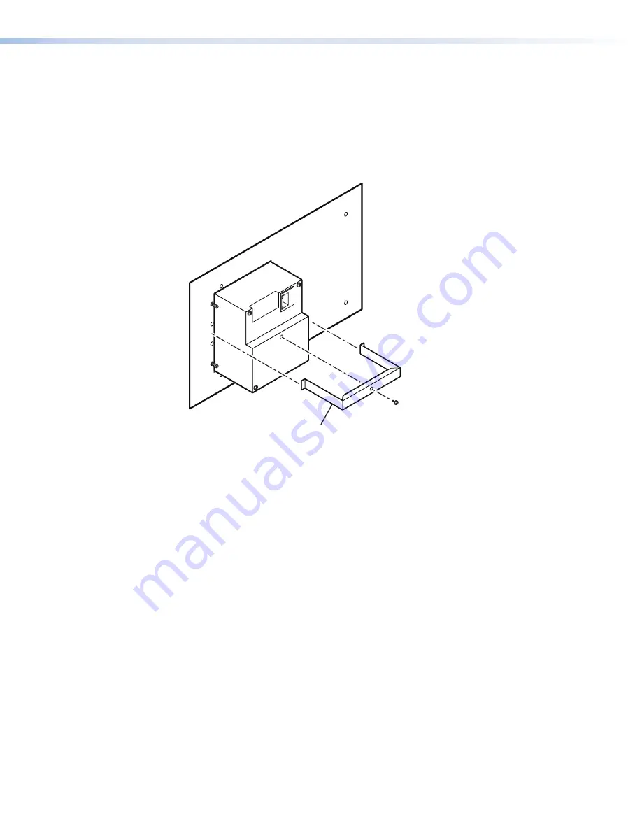
intercoms, the IPI 200 AAP Series intercoms are secured by attaching a clamp bracket to the 
back of the intercom after it has been inserted through the front of the AAP plate.

1. 

Before cables are attached, insert the IPI through the front of the device faceplate or AAP 
mounting frame. Secure the IPI to the faceplate/wall plate by attaching the provided clamp 
bracket.

Extron
IPI 204 AAP

Intercom
(rear view)

Clamp Bracket
(included)

Figure 35. 

Mounting the IPI 200 Series

2. 

Connect cables to the IPI. See 

IPI Rear Panel Features and Cabling

 on page 6.

3. 

Mount the AAP mounting frame or other device to the wall, furniture, or rack panel. Follow 
any special mounting instructions that came with that device.


IPI 100 and IPI 200 Series • Mounting

52

Summary of Contents for MediaLink IPI 100 Series

Page 1: ...01 LAB ADMIN OFFICE HELP DESK CONFIG IN IPI 201 Extron INTERCOM MIC ON PUSH TO CALL HELP DESK CONFIG INTERCOM MIC ON IPI 204 PUSH TO CALL 1 2 3 4 ROOM 101 LAB ADMIN OFFICE HELP DESK CONFIG INTERCOM MI...

Page 2: ...tio Web de Extron www extron com Instructions de s curit Fran ais AVERTISSEMENT Ce pictogramme D lorsqu il est utilis sur le produit signale l utilisateur la pr sence l int rieur du bo tier du produit...

Page 3: ...IP Link Key Minder LinkLicense LockIt MediaLink MediaPort NetPA PlenumVault PoleVault PowerCage PURE3 Quantum SoundField SpeedMount SpeedSwitch System INTEGRATOR TeamWork TouchLink V Lock VN Matrix Vo...

Page 4: ...s interference must be corrected at the expense of the user NOTE For more information on safety guidelines regulatory compliances EMI EMF compatibility accessibility and related topics see the Extron...

Page 5: ...omputer or device responses mentioned in this guide the character 0 is used for the number zero and O represents the capital letter o Computer responses and directory paths that do not have variables...

Page 6: ......

Page 7: ...Command 20 Help Desk Software 21 Introduction to the Software 21 System Requirements 22 Installing the Software 22 Starting the Program 23 Configuring the IP Intercom System 24 Basic Configuration 24...

Page 8: ...IPI 100 and IPI 200 Series Contents viii...

Page 9: ...4 Extron INTERCOM MIC ON IPI 204 PUSH TO CALL 1 2 3 4 ROOM 101 LAB ADMIN OFFICE HELP DESK CONFIG IPI 201 Extron INTERCOM MIC ON PUSH TO CALL HELP DESK CONFIG IPI 204 2 gang IPI 201 2 gang INTERCOM MIC...

Page 10: ...nd installed along with the Global Configurator software About the IP Intercom Modules The Extron MediaLink IPI 104 AAP and IPI 204 four button modules and the IPI 101 AAP and IPI 201 one button modul...

Page 11: ...en in on rooms To satisfy legal and privacy requirements the intercom can play a recurring tone during room monitoring This tone can be turned on or off in the HelpDesk Preferences The status monitori...

Page 12: ...n et l entretien doivent tre effectu s uniquement par un technicien qualifi Ce produit devrait tre utilis avec un bo tier lectrique certifi UL This unit is not to be connected to a centralized DC powe...

Page 13: ...at www extron com For the IPI 200 Series models 1 Connect the LAN port to the local network using a standard network cable with an RJ 45 connector see figure 2 2 Connect power and if required contact...

Page 14: ...ER RELAY C NO AUDIO OUT LAN D D E E F F A A IPI 104 AAP IPI 101 AAP Rear Panel IPI 204 AAP IPI 201 AAP Rear Panel B B C C B B A Intercom port see page 7 D Power see page 8 B AAP mounting screws see pa...

Page 15: ...ith each IPI If you choose to terminate your own cable the cable must be no longer than 100 feet 30 4 m Cables must be terminated to the T586A or T586B standard and both ends of a cable must be wired...

Page 16: ...s une cavit murale The installation shall be in accordance with the applicable provisions of the National Electrical Code ANSI NFPA 70 Article 725 and the Canadian Electrical Code Part 1 Section 16 Ce...

Page 17: ...in this section Single PC to Panel For a simple intercom system connect one or more panels to a PC that serves as the help desk console TCP IP Network Classroom IP 10 XX XX 02 MLC 226 IP AAP IPI 101 A...

Page 18: ...Each console is configured to connect with several intercoms and each intercom is configured to contact up to four consoles TCP IP Network Straight through Network Cable IP 10 XX XX 03 Audio Card Chem...

Page 19: ...of an IP Intercom System In this example panels are configured to communicate directly with each other The software does not need to be running during intercom system operation NOTE Panel to panel mo...

Page 20: ...1 2 3 4 5 6 VOLUME CONFIG IR ON OFF AUTO IMAGE MUTE LAPTOP VCR DVD AUX VIDEO PC MLC 226 IP INTERCOM MONITOR IPI 101 PUSH TO CALL HELP DESK PUSH TO CALL PUSH TO CALL PUSH TO CALL Figure 9 Server Mode...

Page 21: ...V 50mA L MPA 152 R C US LISTED 17TT AUDIO VIDEO APPARATUS SI 3CT LP Ceiling Speakers POWER RELAY C NO AUDIO OUT LAN Figure 10 Intercom with an Amplifier 2 Power on the equipment 3 Make fine adjustment...

Page 22: ...ress the Push to Talk button to speak into the intercom It also lets help desk staff monitor what is happening to determine whether to send security personnel to that room C Microphone Push one of the...

Page 23: ...sfully connected press and hold the button when you speak and release it to allow the other party to speak NOTE You must press and hold an IPI button to speak and to call the help desk or another inte...

Page 24: ...system network administrator 2 Write down the unit MAC address a 12 digit number found on a label on the rear panel of the unit for example 00 05 A6 01 0A 74 3 If the unit IP address has been changed...

Page 25: ...CONFIG port The IP address of the IPI 200 Series intercom unit must be set to the factory default To set an IP address with a GC project file open 1 From the Edit menu select Add Device The Add Devic...

Page 26: ...sover cable between the device and a local PC 2 On the PC locate the TCP IP Properties dialog box Figure 14 TCP IP Properties Dialog 3 Record the current IP address subnet mask default gateway and DHC...

Page 27: ...ce the new IP address and subnet mask are assigned to the device the connection is lost The device can now be connected to your AV network To return the local PC to its original TCP IP settings 1 Clos...

Page 28: ...t To set an IP address using the ARP command 1 Open a command prompt window on a local PC 2 At the command prompt enter arp s IP address MAC address for example C arp s 192 168 254 254 00 05 A6 00 30...

Page 29: ...from the following white papers which can be found at www extron com to ensure optimal network configuration and compatibility for the IP Intercom system IP Intercom Network Impact Statement IP Inter...

Page 30: ...in the sidebar 2 4 Click IP Intercom HelpDesk Software in the sidebar 3 or on the main page 4 If you do not see this option scroll down to the alphabetic menu Click I and navigate to IP Intercom HelpD...

Page 31: ...to find basic information about Log in as User Log in as a HelpDesk Administrator Change the Password Set Up Intercom equipped Extron Devices If you do not wish to see this window when you open the pr...

Page 32: ...ration consult the IP Intercom HelpDesk Help File which can be accessed by clicking Help in the Help menu or by pressing F1 from within the HelpDesk program Basic Configuration Using the Configuration...

Page 33: ...P Device with the Configuration Utility on page 27 Entering the IP addresses manually 1 1 2 2 3 3 4 4 Figure 22 Enter the IP Addresses Manually 1 Select Manually by IP Address from the drop down menu...

Page 34: ...3 A Scan Progress dialog box opens indicating the progress of the scan Figure 23 Scanning the Local Subnet 4 The scan detects only intercoms that are on the same local subnet and adds them to the Int...

Page 35: ...formation is displayed in the Selected Intercom panel Figure 24 Configuration Utility 3 In the Selected Intercom panel the unit administrator password and the IP addresses associated with each of the...

Page 36: ...press and hold down the keyboard spacebar The label on the button changes to TALKING 3 Speak into the headset microphone The Local Mic VU meter oscillates in response to the audio being picked up by...

Page 37: ...om to indicate that the intercom mic is opened and the green MIC ON LED lights 6 Start speaking While the LISTENING button is active an audible signal is heard every ten seconds 7 Deselect the Listeni...

Page 38: ...tton turns green and the intercom devices belonging to that group are highlighted in the Intercom List 5 Activate the Talk mode Talk Mode starting on page 28 When you have finished talking inactivate...

Page 39: ...ox 2 Click on the file button and go to C Program Files Extron IPI wav folder Select the wav files that you wish to be available 3 Click OK to close the Manage Sound Bites box and then click Exit to c...

Page 40: ...panel enter the IP address of the server PC or select it from the dropdown list c Click Apply d Repeat steps a c until all intercoms have been linked to one of the available help desk computers 3 All...

Page 41: ...described in steps 3a to 3e of Setting up a peer to peer network on the previous page The first name on the list will be the first choice HelpDesk If the first PC is busy the next call will be passed...

Page 42: ...Figure 33 Server Mode IPI 100 and IPI 200 Series Help Desk Software 34...

Page 43: ...E The following SIS commands are for use with the IPI 201 and 204 models only Refer to the MLC 226 IP Series Installation Manual for IPI 101 104 series SIS command and control information IPI RS 232 p...

Page 44: ...der the following circumstances If the IPI is off and an RS 232 connection is already set up the PC is cabled to the IPI 200 series unit and a serial terminal emulation program such as HyperTerminal i...

Page 45: ...or file not found E30 Hardware failure followed by colon and descriptor number unsolicited response E31 Attempt to break port pass through when not set Error Response References The following superscr...

Page 46: ...wer case characters may be used interchangeably in the command field unless otherwise specified Commands may be sent back to back without spaces for example 11S0X4Q Numbers can be entered with leading...

Page 47: ...n into the corresponding hexadecimal equivalent xx where xx represents the two character hex byte For example a space hex 20 would be encoded as 20 hex 25 32 30 and a plus sign hex 2B would be encoded...

Page 48: ...n Brazil X4 Password to display on screen response to password query or set When the IPI unit connects to a host device via RS 232 the password X3 itself is the response When the connection is via IP...

Page 49: ...e mode is off On24 1X 1X Exe 1 Executive mode is on View lockout mode status X X X20 X20 Front panel lockout executive mode status 0 off unlocked 1 on disabled front panel locked By default the front...

Page 50: ...1Q 1 01 or Ver01 1 01 Query verbose firmware version information 0Q 0Q X1 X1 X1 responses to commands 2Q 3Q 4Q X1 Version typically listed to two decimal places e g x xx Shows bootstrap factory insta...

Page 51: ...part numbers Request the model name 1I 1I IPI 201 or IPI 204 Request the model description 2I 2I One Button IP Intercom or Four Button IP Intercom Request system memory usage 3I 3I Show amount of mem...

Page 52: ...ading zero is optional Do not use a plus sign Read GMT offset ECZ WCZ X Set daylight saving time24 EX3 CX WX3 CX IpxX3 Read daylight saving time ECX WCX X3 X3 See note below Set DHCP on24 E1DH W1DH Id...

Page 53: ...erbose mode is on default for RS 232 host control responses are echoed to the host and displayed to the user 2 send tagged responses for queries 3 verbose mode is on and tagged responses are sent for...

Page 54: ...pu This clears the user password only Read user password ECU WCU X4 Read connection security level ECK WCK X5 or PvlX5 For X5 11 user 12 administrator NOTES X1 Broadcast subnet address Default 255 255...

Page 55: ...Pmd port Set a direct access port number that does not conflict with any other ports Reset Direct Access port24 E2001MD W2001MD Pmd 02001 This resets the direct access port to port 2001 Disable Direc...

Page 56: ...s HTMLfiles CJ Wcustompages 2F HTMLfiles 2F CJ Dir custompages HTMLfiles In this example a directory called HTMLfiles was created inside the custompages directory Example 3 Eoak CJ W oak 2F CJ Dir oak...

Page 57: ...e and its corresponding file size The last line of the response indicates how much available file space there is E DF WDF filename 1 day date time of upload GMT file size 1 in bytes filename 2 day dat...

Page 58: ...ents E0AE W0AE Est Query number of events running EAE WAE or Enm The response is the quantity of currently running events and it includes leading zeros For example if two events are running the respon...

Page 59: ...hown below Extron PROJECTOR MLC 226 IP AAP 1 2 3 4 5 6 VOLUME CONFIG IR PC AUX VIDEO DVD VCR DOC CAM LAPTOP AUTO IMAGE MUTE ON OFF Extron MLC 226 IP AAP MediaLink Controller Extron IPI 104 AAP Interco...

Page 60: ...nt of the AAP plate 1 Before cables are attached insert the IPI through the front of the device faceplate or AAP mounting frame Secure the IPI to the faceplate wall plate by attaching the provided cla...

Page 61: ...Label Generator Software The Button Label Generator software creates labels that you can place in the translucent covers above the buttons You can create labels with names alphanumeric characters or c...

Page 62: ...the Button Label Generator program click on the desktop icon or open the program from the start menu The Button Label Generator window opens 1 1 2 2 3 3 4 4 Figure 38 Button Label Generator Software 2...

Page 63: ...ing motion of the screwdriver carefully pry the two pieces apart B 3 Replace the label with the new button label C 4 Press the lens cap and diffuser together and reinstall the button assembly into its...

Page 64: ...n and ask for an Application Engineer to receive an RA Return Authorization number This will begin the repair process USA 714 491 1500 or 800 633 9876 Europe 31 33 453 4040 Asia 65 6383 4400 Japan 81...

Reviews: