background image

DXP DVI, DXP DVI Pro, and DXP HDMI Series • Operation

46

Configuration Worksheets

Instead of trying to remember the configuration for each preset, use worksheets to record 
this information. Make copies of the 

blank worksheet

 on page 

48

, and use one sheet 

for each preset configuration. Cross out all unused or inactive inputs and outputs. The 
worksheet is generic for all models of DXP. Disregard or cross out boxes for inputs and 
outputs that your switcher does not have.

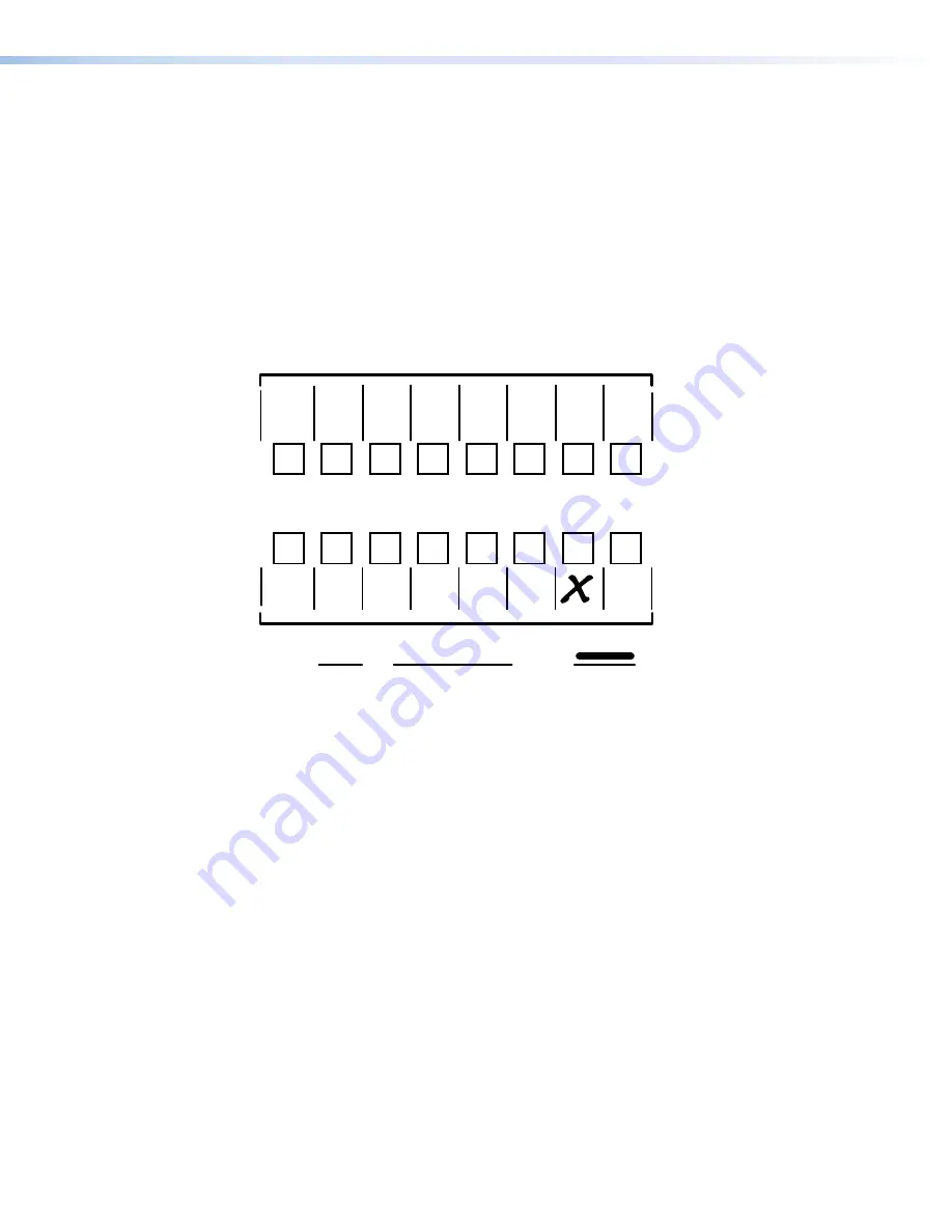
Worksheet Example 1: System Equipment

Figure 

67

 shows a worksheet for a DXP in a fictional organization with the system 

hardware annotated. Output 7 has no connection in this organization, so it has been 
crossed out on the worksheet.

Preset #


Title:  

Video ties:

Fill in the preset number and use colors, dashes, and so forth to make connecting lines.

VTG  

400DVI

VTR

#2

VTR 

#1

Weekly status mtg  

DVI PRO/

HDMI

Camera 

#2

DVI PRO/

HDMI 

Camera #1 

Main

podium

Main hall

#1

Main hall

#2

Podium

monitor

#1

Conf.

Room

Podium 

monitor

#2

Demo

Room

Lobby 

monitor 

Editing

Station

#1

Input  Sources

Output Destinations 

DVI PRO/

HDMI

Camera 

#3

Editing

Station

#2

Figure 67. 

Worksheet Example 1: System Equipment

Inputs include VTRs, editing stations, DVI Pro/HDMI cameras, and an Extron VTG 400DVI. 
Output devices include various DVI Pro/HDMI monitors.
The VTG 400DVI video test generator connected to input 6 enables a video test pattern 

to be sent to one, several, or all output devices for problem isolation or adjustment 
purposes. 

Summary of Contents for DXP DVI

Page 1: ...User Guide DXP DVI DXP DVI Pro DXP HDMI Matrix Switchers DVI DVI Pro and HDMI Series Digital Matrix Switchers 68 2192 01 Rev B 09 12...

Page 2: ...erksam machen da im Inneren des Geh uses dieses Produktes gef hrliche Spannungen die nicht isoliert sind und die einen elektrischen Schock verursachen k nnen herrschen Achtung Lesen der Anleitungen Be...

Page 3: ...e harmful interference to radio communications Operation of this equipment in a residential area is likely to cause interference the user must correct the interference at his own expense NOTE This uni...

Page 4: ...35 17 03 EX X1 X2 X2 X2 CE NOTE For commands and examples of computer or device responses mentioned in this guide the character 0 is used for the number zero and O represents the capital letter o Com...

Page 5: ...Preset 29 Example 6 Recalling a Preset 30 I O Grouping 32 Example 7 Grouping Inputs and Outputs 34 Muting and Unmuting Video and Audio Outputs 36 Example 8 Muting and Unmuting an Output 37 Locking and...

Page 6: ...e Matrix Switcher Help File 101 Creating Button Labels 101 Using the Button Label Generator 102 Replacing Button Labels 103 Blank Button Labels 104 HTML Operation 105 Accessing the Web Pages 105 Speci...

Page 7: ...ls and DXP HDMI refers to the four HDMI models About the DXP DVI DXP DVI Pro and DXP HDMI Series Digital Matrix Switchers The DXP DVI DXP DVI Pro and DXP HDMI series are high performance digital matri...

Page 8: ...atures DXP DVI and DXP DVI Pro Series Inputs and outputs on DVI I connectors HDMI signal support Full support of embedded HDMI audio signals when optional Extron HDMI to DVI adapters are used Audio ca...

Page 9: ...d for easy identification IP Link Ethernet control The DXP matrix switchers can be monitored and managed over a computer network using standard TCP IP protocols IP Link provides for remote selection o...

Page 10: ...pplication Diagram for a DXP 88 HDMI POWER 12V 0 4A MAX HDMI 201 Rx 1 2 HDMI OUTPUT RS 232 PASS THRU Tx Rx POWER 12V 0 4A MAX HDMI 201 Tx RS 232 PASS THRU Tx Rx 1 2 ON 1 2 N A DDC REMOTE LOCAL HDMI IN...

Page 11: ...0 3A MAX 1 2 3 4 Y VID B Y H HV R R Y V G Y B B Y RS 232 RESET DVI I YC SDI R Y C RGB R Y Y B Y YC VID 100 240V 50 60 Hz I N P U T O U T P U T LAN ACT LINK VID 0 3A MAX 1 2 3 4 Y VID R Y H HV R R Y V...

Page 12: ...nsmitter DVI 201 Rx Twisted Pair Receiver DVI Flat Panel Display Short DVI Cable Extron DXP DVI Series DVI Matrix Switcher DVI 200 Tx SERIES DVI INPUT LOCAL OUTPUT DVI 201 Rx SERIES DVI D OUTPUT CONTR...

Page 13: ...igure 4 DXP 88 DVI Pro Rear Panel NOTES The illustration above shows a DXP 88 DVI Pro with eight DVI input and eight DVI output connectors The rear panels of the other DVI Pro models are identical to...

Page 14: ...lug 24 TMDS clock detect Pin Signal Pin Signal Pin Signal 1 TMDS data 2 9 TMDS data 1 17 TMDS data 0 2 TMDS data 2 10 TMDS data 1 18 TMDS data 0 3 TMDS data 11 TMDS data 1 3 19 TMDS data 0 5 2 4 shiel...

Page 15: ...er running the Matrix Switchers Control Program or via the HTML pages that are pre loaded on the switcher see Ethernet Connection on the next page Ethernet connection indicators The Link and Act LEDs...

Page 16: ...ugh cable because no pin or pair assignments are swapped Both ends of the cable can be T568B as shown or T568A not shown RJ 45 Connector Insert Twisted Pair Wires 1 2 3 4 5 6 7 8 Pins Crossover Cable...

Page 17: ...oftware NOTES The switcher can support either the RS 232 or RS 422 serial communication protocol and operate at 9600 19200 38400 or 115200 baud rate See Selecting the RS 232 RS 422 Protocol and Baud R...

Page 18: ...es An input tied to two or more outputs An output can never be tied to more than one input Configuration One or more ties or sets of ties Current configuration The configuration that is currently acti...

Page 19: ...and Indicators All models of the DXP have the same front panel with the same controls and layout The front panel buttons are grouped into two sets with the input and output buttons located on the lef...

Page 20: ...to the selected group Presets Action indication Select a preset in preset mode Lit A preset has already been saved to this location Blinking The preset location is selected to be saved Mutes Action i...

Page 21: ...ndary functions of the four control buttons Primary Functions ENTER PRESET VIEW ESC Action Save changes Select preset mode Select view mode Cancel or escape Indication Blink Save needed Blink Save pre...

Page 22: ...uping mode selects group 2 In I O grouping mode indicates that group 2 is selected With the Enter View and Esc buttons places the switcher in serial port configuration mode Selects 19200 baud for the...

Page 23: ...tes that the Remote RS232 RS422 and the RS 232 Config ports are set to 115200 baud in serial port configuration mode I O Buttons You must select video audio or both before creating or viewing a tie or...

Page 24: ...utton selects between front panel locks lock mode 2 and lock mode 0 With the Video button selects between front panel locks lock mode 2 and lock mode 1 With the Video button commands the front panel s...

Page 25: ...do not support audio only video ties can be created on these models This section contains the steps to follow to create or change a configuration The following subsections contain some examples of con...

Page 26: ...tied can be left on along with new blinking selections or toggled off by pressing the associated output button When the Video and Audio buttons are lit if an input with an audio tie but no video tie i...

Page 27: ...button blinks green to indicate the need to confirm the change OUTPUTS ENTER 3 4 8 Figure 16 Select the Outputs NOTE You can cancel the entire set of ties at this point by pressing and releasing the E...

Page 28: ...oggle video on The button lights green when selected Press the Audio button to toggle audio off The button is unlit or background illuminated when deselected Figure 20 Select Video Only 3 Press and re...

Page 29: ...le 2 Final Configuration Breaking Ties To undo an existing I O tie 1 Press the I O button Video Audio or both for the type of tie you want to break 2 Press the input button whose tie you want to disso...

Page 30: ...e video off The button is unlit or background illuminated when deselected Press the Audio button to toggle Audio on The button lights red when selected AUDIO Figure 26 Select Audio Only 3 Press and re...

Page 31: ...Configuration Viewing a Configuration You can view the current set of video and audio ties using the front panel buttons The view only mode prevents inadvertent changes to the current configuration Vi...

Page 32: ...tton is lit green and the Audio button is lit red After you select an input or output the output buttons light as follows indicating if audio is broken away Amber Video and audio ties Green Video only...

Page 33: ...t 5 are either unlit or background illuminated The output buttons for outputs that are tied to Input 5 light the appropriate color Amber for audio and video ties audio follow Green for video ties vide...

Page 34: ...light green for all video outputs tied to input 5 If no ties are established for input 5 all output buttons return to either unlit or background illumination 7 Press and release the View button to ex...

Page 35: ...sets are retained When a preset is recalled it replaces the current configuration which is lost unless it is also stored as a preset The recalled preset overwrites all of the current configuration tie...

Page 36: ...ntinues to blink PRESET ENTER Press and release the Input 1 button The button blinks to indicate that this preset number is selected but not saved INPUTS 1 2 3 4 5 6 7 8 Figure 40 Select the Preset 4...

Page 37: ...recall the preset INPUTS 1 2 3 4 5 6 7 8 PRESET ENTER Press and release the Input 1 button The button blinks to indicate that this preset number is selected but not recalled Figure 44 Select the Prese...

Page 38: ...put 1 2 Output Camera 3 1 DVS 304 IP DIGITAL VIDEO SCALER ADJUST IR 2 3 4 MENU NEXT VTR MPEG 2 JPEG 2000 1 VTR MPEG 2 JPEG 2000 3 3 input 2 output matrix Monitor Group 2 3 4 4 5 6 Input Output DVS 304...

Page 39: ...en if they include inputs and outputs in different groups Presets that tie inputs and outputs across groups can be created via Ethernet or RS 232 RS 422 These presets are selectable from the front pan...

Page 40: ...oup mode press and hold the Input 1 and Output 1 buttons until all buttons that are not grouped light green approximately 2 seconds 1 2 3 4 5 6 7 8 OUTPUTS 1 2 3 4 5 6 7 8 INPUTS OUTPUTS INPUTS 1 2 3...

Page 41: ...ng and Unlocking the Front Panel Executive Modes on page 39 If front panel lock mode 2 is selected and you try to perform this step the button presses are ignored and the Enter Video and Audio buttons...

Page 42: ...but you cannot change it from the front panel see Locking and Unlocking the Front Panel Executive Modes on page 39 To enable changes to the mute settings set the lock mode to 0 1 Press the Esc button...

Page 43: ...front panel indications if examples 1 2 and 3 have been completed I O AUDIO VIDEO Until you select an input the buttons for all untied outputs light amber if no inputs are tied green if no video inpu...

Page 44: ...audio is selected the output button blinks between red and amber 5 One at a time press and hold the Output 3 button and then the Output 4 button for approximately 2 seconds until each button returns...

Page 45: ...The switcher is shipped from the factory in lock mode 2 Selecting Lock Mode 2 or Toggling Between Mode 2 and Mode 0 NOTES If the switcher is in lock mode 0 or mode 1 this procedure selects mode 2 If...

Page 46: ...ed You must first place the switcher in lock mode 2 then toggle it to mode 0 see Selecting Lock Mode 2 or Toggling Between Mode 2 and Mode 0 on the previous page Resetting There are several methods by...

Page 47: ...1 System Reset Resetting Using the Rear Panel Reset Button The rear panel has a recessed Reset button that initiates various levels of resets For different reset levels press and hold the button while...

Page 48: ...to the factory default Turns DHCP off Turn events off The Reset LED blinks four times in quick succession during the reset Mode 4 enables you to set IP address information using ARP and the MAC addre...

Page 49: ...ease then immediately press and release again IP Settings Reset Mode 4 6 seconds Absolute Reset Mode 5 9 seconds Press and hold the Reset button 3 seconds Events Reset Mode 3 Front panel I O buttons f...

Page 50: ...m the front panel NOTE The Remote RS232 RS422 port settings are protected when front panel lock mode 2 is selected You can view the settings in lock mode 2 but you cannot adjust them from the front pa...

Page 51: ...Audio buttons blink 4 Press and release an input or output button to exit the serial port configuration mode C O N T R O L PRESET ENTER I O VIDEO AUDIO ESC VIEW 5 All Control and I O buttons return t...

Page 52: ...ization so it has been crossed out on the worksheet 1 2 3 4 5 6 7 8 1 2 3 4 5 6 7 8 Preset Title Video ties Fill in the preset number and use colors dashes and so forth to make connecting lines VTG 40...

Page 53: ...put 1 Displayed in the conference room output 4 to the overflow crowd Displayed in the lobby output 8 Displayed in the Demo Room output 6 The presenter has a presentation stored in the VTR input 4 tha...

Page 54: ...eet Form 1 2 3 4 5 6 7 8 Input Sources Output Destinations Preset Title Fill in the preset number and use colors dashes and so forth to make connecting lines Disregard or cross out the input and outpu...

Page 55: ...on page 44 to configure this port from the front panel The DXP has two connectors that can be used for serial control Both ports enable use of SIS commands and the control software The default protoc...

Page 56: ...network administrator If the IP address has been changed to an address comprised of words and characters you can determine the actual numeric IP address using the ping ICMP utility see IP Addressing...

Page 57: ...m other connections or a serial port To receive change notices from the switcher you must enable verbose mode 1 or 3 see the Set verbose mode command in the Command and Response Table for IP specific...

Page 58: ...ults to administrator privileges Qik The switcher initiates the Qik message when a front panel switching operation has occurred Rprnn The switcher initiates the Rpr message when a memory preset has be...

Page 59: ...evice not present E26 Maximum number of connections exceeded E27 Invalid event number E28 Bad filename or file not found E30 Hardware failure followed by a colon and a descriptor number E31 Attempt to...

Page 60: ...lected outputs that relate to each other The DXP switchers support up to 10 rooms each of which can consist of from 1 to 16 outputs X Global preset number 00 32 00 current configuration X Room preset...

Page 61: ...electing one of the categories of EDID files see the EDID table on the next page The EDID of the display connected to an output numbers 1 through the number of outputs on your DXP One of 28 factory lo...

Page 62: ...Default for DXP DVI Pro and HDMI 60 720p 2 channel audio Default 60 13 852x480 60 33 1080i 50 1080p multi channel audio 60 14 852x480 75 34 1080i 60 1080i 2 channel audio 60 15 1024x768 Default for DX...

Page 63: ...bullet point in the notes above 8 4 Out4 In8 RGB Tie Input 8 RGB to Output 4 Tie input to output video only X X Out X In X Vid Video breakaway Example See the second bullet point in the notes above 7...

Page 64: ...t 5 audio and Output 6 video and audio are muted All other outputs are unmuted NOTE The Mut portion of the response appears only when the switcher is in verbose mode 2 or 3 see the Set verbose mode co...

Page 65: ...s in a global preset number before you directly write a global preset to that number ties that are part of the previous version of the specified preset with the same number can become part of the newl...

Page 66: ...d audio output tie X X View Input X to which Output X is tied Example 4 7 Output 4 is tied to Input 7 video and audio View RGB output tie X X Example 7 2 Output 7 is tied to Input 2 RGB View video out...

Page 67: ...nput 2 is tied to Output 3 and Input 7 is tied to Outputs 6 and 7 No input is tied to Output 8 Outputs 9 through 16 do not exist on the DXP so they are shown as having no tied inputs View audio global...

Page 68: ...E 40 2I 1 Input Gri Response s group Input 1 in group 4 2 3 4 5 6 7 8 4 0 1 3 3 0 0 2 Input 2 not grouped Input 8 in group 2 Input 1 group 4 input 2 group 0 ungrouped input 8 group 2 Write output gro...

Page 69: ...PodiumCamNI Nmi1 PodiumCam Name Input 1 PodiumCam Read input name E X NI X1 View the name of Input X Write output name E X X1 NO Nmo X X1 Assign name X1 to Output X Example E 1 Main PJ1NO Nmo1 MainPJ...

Page 70: ...idual room preset and name Reset whole switcher E ZXXX Zpx Clear all ties and presets Absolute resets E ZQQQ Zpq Similar to the Reset whole switcher command plus clear the IP address to 192 168 254 25...

Page 71: ...Query controller firmware version verbose 0Q X2 X2 X2 Provide a detailed status of the Ethernet protocol firmware the controller firmware and any firmware upgrade The firmware that is running is marke...

Page 72: ...files E filenameEF Del filename EDID Extended Display Identification Data Commands Assign EDID data to an input E A X X1 EDID EdidA X X1 Assign EDID file X1 to input X Assign EDID data to all inputs E...

Page 73: ...E O X HDCP X1 View HDCP status X1 for Output X View HDCP status for all inputs E I HDCP X1 X1 X1 n View HDCP status for all inputs View HDCP status for all outputs E O HDCP X1 X1 X1 n View HDCP status...

Page 74: ...ugh 59 X3 GMT offset 12 0 through 14 0 Hours and minutes removed from GMT X3 Daylight Saving Time 0 Daylight Saving Time off or ignore 1 Daylight Saving Time on northern hemisphere 2 Daylight Saving T...

Page 75: ...Data bits 7 8 default 8 X5 Stop bits 1 2 default 1 X5 Port type 0 RS 232 1 RS 422 X5 Verbose mode 0 clear none default for Telnet connection 1 verbose mode default for RS 232 or RS 422 connection 2 ta...

Page 76: ...ddress E X3 CI Ipi X3 Read IP address E CI X3 Read hardware address E CH X3 Read number of open connections E CC Icc X3 Set subnet mask E X3 CS Ips X3 Read subnet mask E CS X3 Set gateway IP address E...

Page 77: ...ipient 8 JSmith will receive fail missing and fixed and restored messages for all inputs Set DHCP on or off E X4 DH Idh X4 Read DHCP on off status E DH X4 Set serial port parameters E X4 X4 X4 X5 X5 C...

Page 78: ...d on a DVD To install the software from the DVD to your computer hard drive load the DVD in your computer The disc should start automatically if it does not run Launch exe from the DVD drive Follow th...

Page 79: ...ou are logged on via the Ethernet port as an administrator editing settings unique to the Ethernet interface see IP Setup on page 79 for more details Special Characters The HTML language reserves cert...

Page 80: ...ted Emulate click OK and see Using Emulation Mode on page 99 3 If you selected IP LAN in step 2 the IP Connection window opens Figure 73 Address and Password Entry for IP Connection a Check the Extron...

Page 81: ...assword entry display for you to enter another password 4 The Extron Matrix Switchers Control Program matrix window appears The window displays the current configuration of the attached matrix with nu...

Page 82: ...matrix window the inputs and outputs are represented by boxes You can assign icons that represent your connected devices to each numbered input and output box 1 Click on an input or an output box The...

Page 83: ...On the matrix window you can create dissolve and view input to output ties as follows To create a tie click and drag from an input box to an output box If Hold Verify Changes has been selected from t...

Page 84: ...sition the cursor over that device in the matrix window A pop up window opens showing the input and output numbers names if captions were specified details on the connections to that device and the fr...

Page 85: ...sconnect your computer from the switcher Matrix IP Address Gateway IP Address Subnet Mask Use DHCP check box Administrator Password NOTES Extron recommends editing the settings on this screen using th...

Page 86: ...e Descriptor field contains the name used as the from information when the DXP switcher e mails notification of its failed or repaired status The default name or descriptor shown in this field is a po...

Page 87: ...via RS 232 or RS 422 to edit this field Hardware Address field The hardware MAC address consists of six pairs of alphanumeric characters in the format xx xx xx xx xx xx The MAC address is hard coded...

Page 88: ...c cursor becomes a text cursor in the set offset field 2 Edit the field as desired to set the proper offset Leading zeros are optional Some time zones are on the half hour 30 minutes 3 Press the Tab k...

Page 89: ...The graphic cursor becomes a text cursor 2 Make any desired changes to the case sensitive user password 3 Press the Tab key on the keyboard or click in another field to exit the User Password field 4...

Page 90: ...DXP E mail The radio buttons and check boxes associated with each address field permit the administrator to specify specific e mail requirements for each recipient Edit these fields and controls as f...

Page 91: ...ion This is not the page on which to insert your own HTML pages See Uploading HTML Files on page 87 to insert custom HTML pages 1 Go to the Extron web site www extron com and download the latest firmw...

Page 92: ...the attempted firmware upload fails for any reason the switcher reverts to the factory installed firmware 5 Click Open A confirmation prompt window opens reminding you that loading the selected s19 fi...

Page 93: ...a the rear panel Remote RS232 RS422 port the front panel Config port or the Ethernet port 2 Start the Matrix Switcher Control Program and connect to the DXP switcher see steps 1 through 4 under Using...

Page 94: ...preset number when prompted to do so Delete Deletes the selected preset Take Allows you to save to file any changes made to the displayed configuration Cancel Returns to the previous screen undoing a...

Page 95: ...and output device icons You can drag any of these icons to the input and output boxes To remove an icon from an input or output box drag an empty square from this list to the input or output box Figur...

Page 96: ...n output to mute then select the Video check box in the Mute field To mute all outputs at once select the All check box Figure 86 Channel Mute Settings Window EDID settings Opens the EDID Configuratio...

Page 97: ...a user defined file User assigned EDID 37 through 40 Figure 88 EDID Record Viewer HDCP status DVI Pro and HDMI models only Opens the EDID Configuration window which contains a diagram indicating which...

Page 98: ...l view of the status of the matrix switcher including the power supply status and the individual voltages the internal temperature the Remote RS232 RS422 port configuration the number of IP connection...

Page 99: ...name Figure 91 Names for Presets Window NOTES Preset names are limited to 12 upper and lowercase alphanumeric characters space and the _ and characters The following characters are invalid or not rec...

Page 100: ...tput groups 1 Drag two or more of the small boxes representing inputs or outputs to one of the input or output Group boxes You can drag boxes to a Group box from the Free section or from another Group...

Page 101: ...Click Take to establish the rooms NOTE A room is a subset of outputs that are logically related to each other as determined by the operator The DXP switcher supports up to 10 rooms each of which can c...

Page 102: ...tion changes you make take effect immediately without the need to click a Take button When you select this option the Take and Cancel buttons are removed from the matrix window Hold Verify Changes Del...

Page 103: ...Ties Shown as Crosspoints Signal detection options Provides a submenu that allows you to set the input signal detection DSVP feature to do one of the following Automatically refresh the display every...

Page 104: ...report all configuration and setting changes to the Remote RS232 RS422 or Ethernet port connection through which this selection was made These reports allow the Matrix Switcher Control Program to tra...

Page 105: ...A nxn Firmware Ver Firmware version to second decimal place LoggedOn as Administrator or User Connection For RS 232 or RS 422 Com n baud rate or for IP IP IP address About this Program Opens a window...

Page 106: ...e 99 Selecting an Emulation File NOTE Selecting the Demo mtx file provides a sample of a completed matrix setup Selecting the New ini file or clicking Cancel provides a blank setup screen to get you s...

Page 107: ...lect the MATRIX Switcher Help icon shown at right Within the Matrix Switcher Control Program select Contents from the Help menu on the matrix window From within the Matrix Switcher Control Program pre...

Page 108: ...xtron Electronics group or folder The Button Label Generator window opens Figure 102 Button Label Generator Window 2 From the Systems pull down menu select DXP 44 88 for the layout that most resembles...

Page 109: ...igure 103 2 Locate the small corner notch on the clear lens cap and slide the screwdriver between the lens cap and the diffuser see b in figure 103 3 Using a rotating motion of the screwdriver careful...

Page 110: ...DXP DVI DXP DVI Pro and DXP HDMI Series Matrix Software 104 Blank Button Labels...

Page 111: ...Tools Internet Options Connections LAN Settings clear the Use a proxy server check box then click OK Accessing the Web Pages Access the HTML pages as follows 1 Start the web browser program 2 Click i...

Page 112: ...includes a specific file name such as 10 13 156 10 file_name html the switcher downloads that HTML page If there is a file in the DXP memory that is named index html the switcher downloads index html...

Page 113: ...individual voltages and serial port status if applicable The System Status page is the default page that the switcher downloads when you connect to it You can access the System Status page from other...

Page 114: ...h Digital Content Protection HDCP page To display the DSVP statuses select the Status tab then click DSVP and HDCP link on the left sidebar menu to display the DSVP and HDCP page NOTE The DXP DVI non...

Page 115: ...P Addressing on page 125 for basic information about IP addresses and subnetting Figure 107 System Settings Page On password protected connections there are two levels of protection administrator and...

Page 116: ...in the switcher flash memory Valid IP addresses consist of four 1 2 or 3 digit numeric sub fields separated by periods Each field can be numbered from 000 through 255 Leading zeros up to 3 digits tot...

Page 117: ...Mean Time GMT from the Zone menu The Zone field identifies the standard time zone that has been selected and displays the amount of time in hours and minutes that the local time varies from the GMT i...

Page 118: ...word or the User Password field 2 Enter the password again in the Re enter Password field to the right Characters in these fields are masked by four bullets 3 Click the Submit button at the bottom of...

Page 119: ...gs and for each row of the e mail notification settings 1 Click the Edit button at the right of the field to make the field available for editing The button changes to Save 2 After editing the setting...

Page 120: ...combination of letters numerals spaces and symbols except the comma and the single and double quotation marks and For the password you can use all characters except the comma The user name and passwo...

Page 121: ...n tab Figure 112 Firmware Upgrade Page NOTE The Firmware Upgrade page is only for replacing the firmware that controls all switcher operation To insert your own HTML pages see File Management Tab on p...

Page 122: ...rmware files must have the file extension S19 Any other file extension is not a firmware upgrade Uploading files with a different extension could cause the DXP to stop functioning NOTE The original fa...

Page 123: ...haracters and underscores NOTE The following characters are invalid or not recommended in file names and space To upload files from the server 1 Click the Browse button to the right of the file name f...

Page 124: ...name to open it then use the Uploading Files procedure on the previous page To exit the directory click root to go to the top directory level or back to go up to the next directory level Other File M...

Page 125: ...iew Ties screen consists of the following major sections Set View Ties Consists of a matrix of input rows and output columns selection buttons To create a tie using this screen 1 Move the mouse over t...

Page 126: ...ideo Audio button A color fill is added to the selected signal type button Video Only is filled with green Audio Only red and Video Audio amber 2 Click the Mute button to the right of the desired outp...

Page 127: ...preset click one of the unassigned buttons To overwrite an existing preset click its button 3 Enter a name for the preset in the text field NOTES Preset names are limited to 12 characters Valid chara...

Page 128: ...84 DVI Pro DXP 88 DVI Pro 60 875 01 60 1009 01 60 876 01 60 877 01 DXP 44 HDMI DXP 48 HDMI DXP 84 HDMI DXP 88 HDMI 60 880 01 60 1010 01 60 881 01 60 882 01 DXP 44 DVI DXP 88 DVI 43 265 01 43 266 01 I...

Page 129: ...Pro 75 75 22 8 m Standard Speed 26 650 75 HDMI Pro 100 100 30 4 m Standard Speed 26 650 100 HDMI Pro 125 125 38 m Standard Speed 26 650 125 HDMI Pro 150 150 45 7 m Standard Speed 26 650 150 HDMI Pro 1...

Page 130: ...gs when addressing this concern Reliable earthing grounding Maintain reliable grounding of rack mounted equipment Pay particular attention to supply connections other than direct connections to the br...

Page 131: ...e network identifier and HHH refers to the host identifier Choosing IP Addresses If the computer and the DXP are directly connected or connected via their own independent network follow the guidelines...

Page 132: ...set the correct value for the subnet mask The basic values depend on the class of IP address being used Class Name Subnet Mask Class A 255 0 0 0 Class B 255 255 0 0 Class C 255 255 255 0 See Subnetti...

Page 133: ...rects the command to return the web address rather than the numeric IP address At the prompt enter ping a IP address The display that the computer returns is similar to the Ping response shown in figu...

Page 134: ...ogin User No further prompts are displayed until you disconnect from the DXP switcher Escape character and Esc key Many SIS commands include the keyboard Esc key Consequently some confusion may exist...

Page 135: ...essary in order to understand the interaction of the DXP switcher and the mail server gateway To understand subnetting at the level required to install and operate the DXP switcher you must understand...

Page 136: ...device IP address see figure 123 below The octets of each address are compared or not depending on the value in the related subnet mask octet If a subnet mask octet contains the value 255 the related...

Page 137: ...nd Africa Extron Europe Hanzeboulevard 10 3825 PH Amersfoort The Netherlands China Extron China 686 Ronghua Road Songjiang District Shanghai 201611 China Asia Extron Asia 135 Joo Seng Road 04 01 PM In...

Reviews: