19
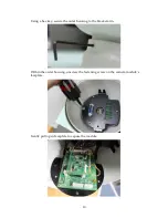
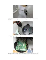
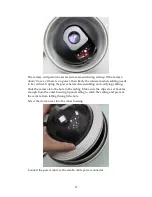
Place the inner housing into the outer housing. Secure the inner housing to the
outer using the 3 screws provided.
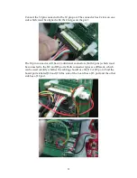
Connect the 30 pin connector to the 30 pin port. The connector has 2 slots on one
side which must be aligned with the 2 ridges on the port
The 30 pin connector will have 2 additional connectors (both 2 pins) which must
be connected to the J12 and J13 ports. Both connector types are different, which
Summary of Contents for EV6250A Series
Page 1: ...EV6250A Series Speed Dome IP Camera Assembly Guide Version 6 3...
Page 8: ...8 Insert the combo cable connectors into the top of the outer housing into the camera module...
Page 9: ...9 Screw the outer housing into the bracket arm by turning the housing from left to right...
Page 13: ...13 The housing s camera saddle points are highlighted below...
Page 30: ...30...


