20
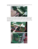
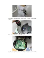
can be used identify whether the cabling should use the J12 or J13 port. Find the
board ports labeled J12 and J13.One side of the board has a J13 port and the other
side has a J12 port.
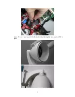
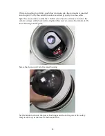
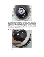
Close the camera module and screw the fastening screw to secure the module’s
faceplate.
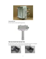
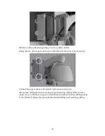
Place the inner housing into the outer housing.
Summary of Contents for EV6250A Series
Page 1: ...EV6250A Series Speed Dome IP Camera Assembly Guide Version 6 3...
Page 8: ...8 Insert the combo cable connectors into the top of the outer housing into the camera module...
Page 9: ...9 Screw the outer housing into the bracket arm by turning the housing from left to right...
Page 13: ...13 The housing s camera saddle points are highlighted below...
Page 30: ...30...

