12
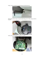
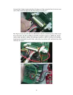
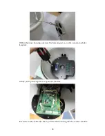
Close the camera module and screw the fastening screw to secure the module’s
faceplate.
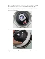
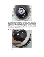
Remove all packaging material from the within the camera dome. Ensure all
packaging has been removed; a failure to do so will prohibit camera movement
and potentially damage the camera.
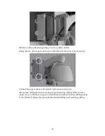
Insert the camera into the inner housing. The camera’s blue connector must be
aligned with the blue port on the camera module’s faceplate within the inner
housing.
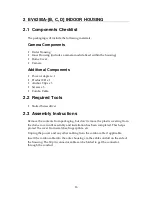
Ensure the 2 camera mounts slide into the inner housing’s camera saddle.
The 2 mounts are on the side are located at the base of the camera.
Summary of Contents for EV6250A Series
Page 1: ...EV6250A Series Speed Dome IP Camera Assembly Guide Version 6 3...
Page 8: ...8 Insert the combo cable connectors into the top of the outer housing into the camera module...
Page 9: ...9 Screw the outer housing into the bracket arm by turning the housing from left to right...
Page 13: ...13 The housing s camera saddle points are highlighted below...
Page 30: ...30...

