27
NONE
Blue/White
NONE
Blue
RS485-
Brown/White
RS485+
Brown
The adapter should be connected to the black line.
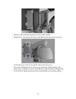
Using the 4 screws provided, secure tube arm to the junction box.
If the device address requires modification, adjust the dip switch settings located
on the base of the PTZ camera. Refer to section 5 for dip switch settings.
Summary of Contents for EV6250A Series
Page 1: ...EV6250A Series Speed Dome IP Camera Assembly Guide Version 6 3...
Page 8: ...8 Insert the combo cable connectors into the top of the outer housing into the camera module...
Page 9: ...9 Screw the outer housing into the bracket arm by turning the housing from left to right...
Page 13: ...13 The housing s camera saddle points are highlighted below...
Page 30: ...30...


