14
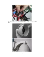
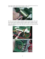
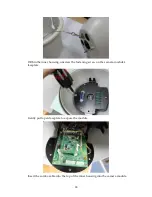
While not pushing too firmly, push down to make sure the connector is inserted
into the port. Verify the camera mounts are settled properly into the saddle.
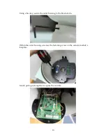
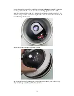
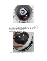
Spin the camera dome to find the 2 slotted screw heads on the base inside of the
camera; using a slotted screwdriver tighten the screws to secure the camera to the
inner housing camera plate.
Screw the dome cover into the inner housing
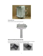
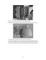
Set the bracket arm into the power box hinges and hook the power box safety
clasp to the loop in the base of the bracket arm.
Summary of Contents for EV6250A Series
Page 1: ...EV6250A Series Speed Dome IP Camera Assembly Guide Version 6 3...
Page 8: ...8 Insert the combo cable connectors into the top of the outer housing into the camera module...
Page 9: ...9 Screw the outer housing into the bracket arm by turning the housing from left to right...
Page 13: ...13 The housing s camera saddle points are highlighted below...
Page 30: ...30...

