26
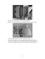
: Insure electrical power has been disconnected before proceeding with the
electrical wiring and junction box configuration.
Connect AC power to AC IN, ground, and camera power cable to power block
terminal.
Connect remaining cabling. The table below describes the DI/DO & RS485
cabling using the adapter.
Function
Line Color
DI-
Orange/White
DI+
Orange
DO+
Green/White
DO-
Green
Summary of Contents for EV6250A Series
Page 1: ...EV6250A Series Speed Dome IP Camera Assembly Guide Version 6 3...
Page 8: ...8 Insert the combo cable connectors into the top of the outer housing into the camera module...
Page 9: ...9 Screw the outer housing into the bracket arm by turning the housing from left to right...
Page 13: ...13 The housing s camera saddle points are highlighted below...
Page 30: ...30...


