


27
PREP
ARING FOR OPERA
TION
SETUP
SETUP
Page 3
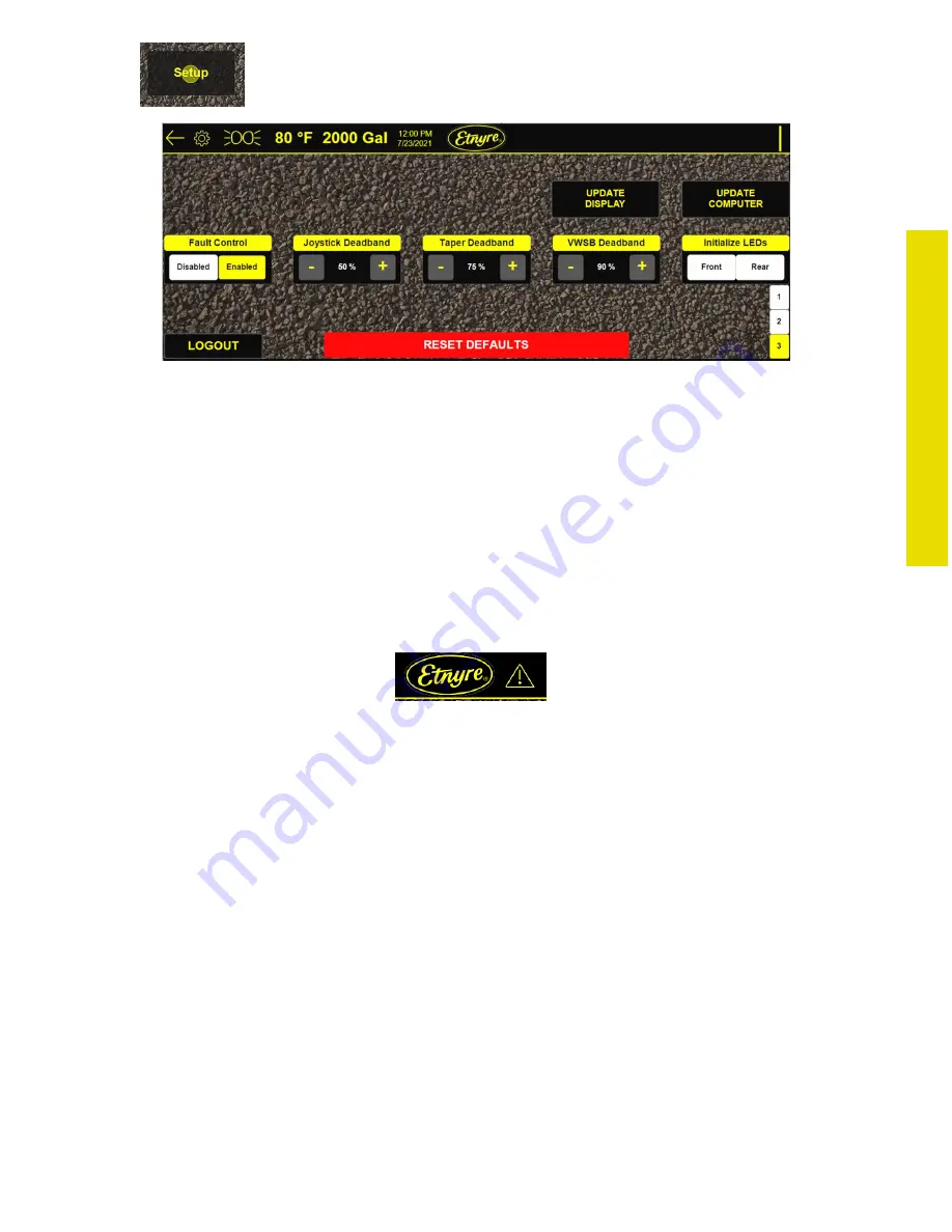
USB / Computer Update:
To update the display or computer program, you will receive specific update files from an Etnyre Service mem
-
ber and must put them on an 8 GB flash drive formatted FAT32. Press the UPDATE DISPLAY or UPDATE COM
-
PUTER buttons to go to the update screens. Instructions are given in Appendix C (Page 95).
Fault Control:
Fault Control can be enabled or disabled. If disabled, faults will continue to log in the display, but will not be
shown in the display. This is not saved to computer memory, and after a power cycle, always begins at enabled.
For safety purposes, if fault control is ever disabled, it will re-enable itself after 30 minutes. Fault control is also
enabled with the Reset Defaults button in Setup. While fault control is disabled, a warning icon will show in the
header indicating it will not display any faults.
Deadband:
The deadband of the joysticks, taper thumbwheels, and variable spray bar thumbwheels can be adjusted. A
deadband of 50% means the device is not active until it is halfway between its center and maximum position.
A smaller deadband means the device is active closer to its center, and a larger deadband means the device is
active closer to its maximum position. The Reset Defaults button set these to their default values:
• Joystick Deadband
50%
• Taper Deadband
75%
• VWSB Deadband
90%
It is recommended to make the Taper and VWSB Deadband relatively high (>50%). When these thumbwheels
are released from their maximum position, they may “spring back” too far and activate on the opposite side.
Initialize LEDs:
The Initialize LEDs control buttons will tell the computer a new LED tank level module is connected to the CAN
bus. If the distributor is shipped from factory with an LED tank level only at the rear of the machine, Rear will be
solid, and Front will be flashing. If you wish to add a second LED tank level module (“Front” or any location you
choose), you must disconnect the Rear module from the CAN bus, connect the new module, hold the Front but-
ton for 5 seconds, and cycle power, before reconnecting the Rear LED module. Both “Front” and “Rear” should
then be solid, indicating the computer sees two unique LED modules.
Figure 28 - Page 3 of Setup Screen
Setup
Figure 29 - Faults Disabled Icon


