background image


Hardware Mounting 


40  


We.R System 


Symptom 

Solution 

Status LED on the 
Control Panel is orange 

(communication lost)


For Ethernet systems 

1.


Verify that the Control Panel is connected to the home 
network switch/router via the network cable. Use the 
network cable provided in the We.R kit only 

2.


Perform a verification test to ensure that your internet 
service is working properly. Connect your 
computer/laptop to the router/modem via the provided 
Ethernet cable. An indication that the internet is 
available should appear 

3.


Verify that your connection to the internet is a direct 
connection and not a dialup connection. If a 
Connection dialog appears on your screen after 
opening your browser, and the dialog requires a 
username password before establishing a proper 
connection, you are using a dialup connection. If you 
open your browser and your Home page opens with no 
connection dialog, you are using a direct connection 

4.


Verify that port 43001 is open in the home’s router 
firewall. You can check port 43001’s availability as 
follows:  
Press Start > Run, and type CMD in the text field. A 
terminal screen is displayed. Type the following: 
telnet wersys.com 43001 
in the terminal screen. The terminal screen should 

appear with no errors (see screenshot in 

Appendix E 

on page 52) 

For Windows 7, enable the telnet checkbox, see 

Appendix F Enable the Telnet Program in Windows 7, 
on page 54 
 

For GSM systems 

5.


Verify that the SIM card is inserted correctly and has 
no data limitations, such as expired, prepaid, etc  


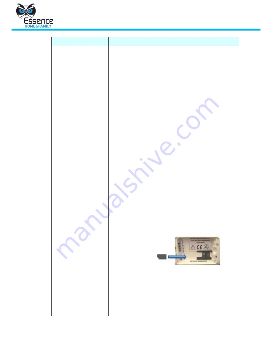
SIM Card Placement 

To access the SIM card, open the back cover of the 
Control Panel and insert the SIM card, face down, as 
illustrated above. Refer to the graphic representation, 
next to the designated SIM location, for further 
assistance. 

6.


Call your GSM provider for possible network 
infrastructure issues


Summary of Contents for We.R

Page 1: ...Part of the Essence Group Version 2 5 October 2012 Home Family Management Solution User Manual...

Page 2: ...rinting reuse reproduction adaptation distribution or translation without the prior written permission of Essence We R Home Family Management Solution Ltd is prohibited The information included in thi...

Page 3: ...Only Web 14 4 2 Manage Devices Web 14 4 2 1 Viewing Information about Devices in the System 15 4 2 2 Adding a New Device 15 4 2 3 Adding a New Key Fob Device 15 4 2 3 1 Wizard Dialogs for Adding a De...

Page 4: ...Appendix A Power Up Devices Peripherals 29 Appendix B Troubleshooting 32 Appendix C Technical Specifications 33 Appendix D Frequent Asked Questions 39 D 1 Control Panel 39 D 2 Magnet Detector MGL 42...

Page 5: ...types of components the Control Panel and the peripheral devices devices that are alarm triggers Throughout this book peripherals may be referred to as devices Keep the system components away from we...

Page 6: ...Panel power cord Square Battery Pack M8000BAT Control Panel backup power source Additional devices may be purchased from your local distributor as needed Prerequisites Before starting the We R system...

Page 7: ...ocket on the back of the Control Panel and then into a network socket on a wall If there is no internet connection available via the Ethernet cable the SIM card will be used as the primary connection...

Page 8: ...sessions accessing the We R system management software just enter your login information email address and password and click Login 1 From a web browser go to the We R web application as specified by...

Page 9: ...screen is displayed see Figure 5 Enter the 8 digit serial number recorded earlier see Appendix G Figure 5 Serial Number Registration Screen and Follow up Screen Click Next Enter your personal details...

Page 10: ...rify the APN information Then click APN Settings Registration The APN Information screen is displayed Alternatively from within the application browser click the Settings button at the top right of th...

Page 11: ...placed in the Control Panel The number must include the international format country code area code phone number sample 14035554567 Control Panel serial The manufacture assign serial number of the Con...

Page 12: ...artphone go to Android Market and download the We R application 3 1 1 Access the We R System Remotely Select the We R application and identify yourself to the system with your 4 digit application code...

Page 13: ...reen 4 1 2 Adding a New User to the System Web 1 Click Add New User A New User row is added to the list 2 In the New User information area to the right of the list enter the new user s information All...

Page 14: ...k Add The user is added to the system 4 1 3 Removing a User from the System Web 1 Select a user from the User list 2 Click Remove User The user is removed from the list and no longer has access to the...

Page 15: ...he roll down menu A wizard guides you through the process You have 3 minutes to complete the wizard instructions click Save before the wizard times out 2 Follow the instructions and enter the relevant...

Page 16: ...Device The We R wizard for adding devices to your system consists of the following dialogs Follow the instructions and click Finish in the last dialog to complete the process This section compares th...

Page 17: ...owing you to monitor and protect zones when you and members of your family are at home For example monitor your medicine cabinet Simply associate the medicine cabinet door sensor with the day arm scen...

Page 18: ...ystem is armed the device alarm action reverts to its primary assigned action 4 2 4 Removing an Existing Device 1 From the Device screen select a device in the Device list 2 Click Remove Device 3 Conf...

Page 19: ...personal remote control device that allows you easy access to basic We R system features Figure 16 Key Fob Face Table 1 Key Fob Buttons and LEDs No Description 1 Full Arm button and LED 2 Disarm butto...

Page 20: ...rt duration System disarmed Night Arm On Red short duration System is partially armed according to the night scenario Day Arm On Red short duration System is partially armed according to the day scena...

Page 21: ...ages and video be taken on a selected device 5 3 Manage Histories Mobile 5 3 1 Viewing Device Histories Mobile On the Main Status screen of the We R Mobile application click History The device histori...

Page 22: ...Dashboard screen provides a central location for key elements of your We R system The Dashboard is organizes so that system information is easily accessible When accessing your system this most likely...

Page 23: ...tection Day Arm The system protects and monitors designated hazardous zones This scenario is used mostly for childcare and safety allowing you to monitor and protect zones like medicine cabinet swimmi...

Page 24: ...lication if you are logged in and on your mobile phone through the We R Mobile application Upon receipt of an Alarm notification you have the following options Watch Video View images from the IPDs in...

Page 25: ...ndoor Photo Detector IPD 1 Peel off the mounting tape s protective covering to mount the IPD spherical lens pointed down on a wall about 220 cm above the floor and at least 10 cm below the ceiling Pla...

Page 26: ...tections will activate the device 9 3 PIR and IPD Operational Modes The We R system has 2 operation modes for PIR and IPD devices Walk Test Mode A test mode which occurs after the device powers up ins...

Page 27: ...ates that the device elements are out of range or misaligned i e the door is open Figure 24 Window Door Sensor Mounting Diagram Best Practice The distance between the 2 components should be no more th...

Page 28: ...ing 28 We R System 2 To detach the device from the wall in case of battery replacement or any other maintenance activity press the white lock at the bottom of the device and slide the device upwards s...

Page 29: ...tery cover from the IPD 2 Insert 2 AA batteries For the next 10 minutes the red light in the IPD may glow periodically as the device conducts a series of tests 3 Replace the battery cover and mounting...

Page 30: ...er A 3 Indoor Siren 1 Remove the battery cover from the Indoor Siren see Figure 28 2 Insert 4 AA batteries The siren provides an audio indication that it is operational 3 Replace the battery cover on...

Page 31: ...s on the battery cover and the back of the device are aligned and then remove the cover Figure 30 Key Fob Battery Cover 2 With the Battery side marked facing up insert the battery into the battery Key...

Page 32: ...typically take about 5 minutes g Log in to the We R system and try to activate the device again h If the LED on the front of the Control Panel does not change to green and using only cellular connect...

Page 33: ...160 grams 45 grams batteries Motion Detector PIR Size H 50mm L 114mm W 60mm Weight 90 grams 30 grams batteries Key Fob SIZE WEIGHT Size H 10mm L 60mm W 40mm Weight 25 grams incl battery Indoor Siren S...

Page 34: ...operation period up to 36 months 4 AA alkaline batteries Window Door Sensors Long operation period up to 24 months 1 AA alkaline battery Tag Reader 3 AA alkaline batteries only for the Tag Reader Lon...

Page 35: ...e range with Alkaline batteries 20 C 50 C with Lithium batteries 20 C 60 C Operating Ambient Temperature range with Alkaline batteries 0 C 50 C with Lithium battery 5 C 60 C Humidity Up to 95 non cond...

Page 36: ...50 C with Lithium batteries 20 C 60 C Operating Ambient Temperature range with Alkaline batteries 0 C 50 C with Lithium battery 5 C 60 C Humidity Up to 95 non condensing Communication Control Panel Up...

Page 37: ...c appliances Window Door Up to 500m RF range open air ECOP bi directional radio protocol onboard Modulation and Frequency DSSS 2 4 GHz Indoor Photo Detector Up to 500m RF range open air ECOP bi direct...

Page 38: ...ation Temperature compensation for the IR Key Fob N A Window Door Tamper Alarm when detached from surface Data Security 128bit AES encryption Unique electronic serial number Supports automatic over th...

Page 39: ...uick resolutions D 1 Control Panel Symptom Solution Initial attempt to bring the We R system online fails and the Control Panel indication LED is OFF In the Control Panel check the battery power level...

Page 40: ...nection If you open your browser and your Home page opens with no connection dialog you are using a direct connection 4 Verify that port 43001 is open in the home s router firewall You can check port...

Page 41: ...Registration The APN Information screen is displayed APN Information Screen After completing the APN Information screen click Send SMS to Panel The information is relayed to the Control Panel via SMS...

Page 42: ...battery cover in the slit at the bottom right of the battery container for a few seconds Remove Static Electricity from the Siren Alternatively remove the battery cover and then return it to its origi...

Page 43: ...inserted correctly with the and polarity observed 2 Verify the magnet part of the detector has not lost its magnetism The detector status LED is red but there has been no status change to the magnet d...

Page 44: ...ess telephone base D 3 Indoor Photo Detector IPD Motion Detector PIR Symptom Symptom The IPD PIR does not detect or record images Check the following 1 An icon on the web application displays a low ba...

Page 45: ...in a new location The intent is to resolve any RF interference The IPD camera flashes periodically 1 This may not be an issue an intruder may have been detected 2 Check for any damage to the device t...

Page 46: ...oring station by looking at the low battery event entry on the right side of the web application replace the battery Lithium battery only All the LEDs are flashing This may not be an issue check the h...

Page 47: ...agent Receiving invalid serial number message during the first time registration procedure 1 Verify that the status LED on the Control Panel is green 2 Verify that you have entered the correct serial...

Page 48: ...ss F5 to refresh the We R web application screen There is no video from a live camera feed in the dashboard 1 Check that the camera is working correctly i e the notification LED is blinking 2 Verify t...

Page 49: ...Arm Night Arm does not work 1 Verify that the Control Panel is online and the status LED is green 2 Verify that none of the system devices has had their Tamper mechanism triggered If a device has bee...

Page 50: ...e via the We R web application A small icon will appear in the upper right hand corner of the device s graphical representation This icon will provide a quick determination as to the cause of the issu...

Page 51: ...nt Event list in the web application D 7 2 Web application browser visibility When viewing the We R web application the browser resolution should be 100 percent Anything higher i e 120 will result in...

Page 52: ...System Appendix E Port Checking To check the availability of port 43001 follow these steps 1 Click Start Run and type cmd in the text field 2 Click Enter The Window terminal screen is displayed 3 Typ...

Page 53: ...is unsuccessful an error message appears This means that port 43001 is blocked and needs to be opened on the router To unblock a port refer to your home router configuration documentation Note If you...

Page 54: ...button and then click Control Panel Programs Under Programs and Features click Turn Windows features on or off The Windows Features Dialog is displayed If you are prompted for an administrator passwor...

Page 55: ...ol Panel S N Owner Name Owner Email Password User Code for mobile phone usage Mobile Phone Number including country and area codes For More Information If you should encounter any problems or have any...

Reviews: