background image


Operating of the Machine 


Paraquda   Startup & Safety 

© Essemtec AG 

4-69


000

00

03/

11

  /  

N

ov

emb

er 4

, 2

01


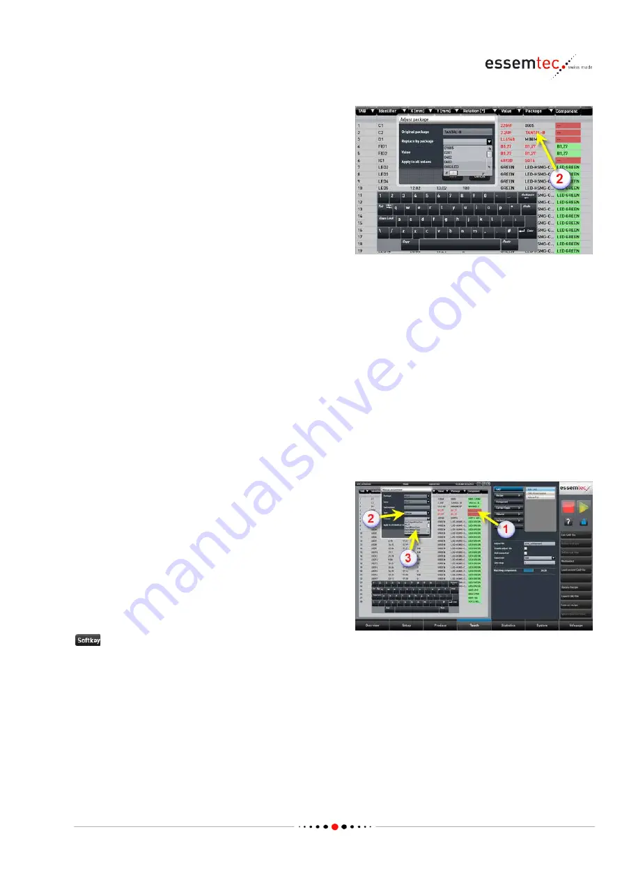
The package changes to red (2). That means no 
package with this name exists within the 

machine environment. There are two 

possibilities:  


The same package already exists but bears 
another name (e.g. Al_ELKO instead of 

ALU_ELKO). In this case click the red 
package name. The pop-up window Adjust 
package
 opens. Click on the parameter 

Replace by package. In the drop down list, 
all known packages are listed. Select the 

correct package. Click on the parameter 

Value. In the drop down list all known 
values are listed. Select the correct value (if 

the correct value is not listed, leave it as is, 

later on continue with the step 'Define 
Component'. Save the new replacement. All 
original packages with the given value are 

replaced by the new name. If all original 

packages with any value should be replaced 
by the new name, check Apply to all values 
before saving.  


The package does not exist, even not with 
another name. In this case continue with the 

step 'Define Package' described below.  


The fiducial changes to red (2). That means no 
fiducial with this name exist within the machine 

environment. Go to step 'Create new Fiducial' in 

chapter 'Define Components' (pag

4-56

) to 

create a new one.  

If an adequate fiducial exist on the machine (see 

Teach - Fiducial) then click on the red 
component field of the appropriate fiducial row 
(1). Select Type Fiducial (2) and select the 

adequate fiducial out of the drop down list (3).  

Save 


Summary of Contents for Paraquda

Page 1: ...Paraquda Startup Safety Manual Object No Index 0000003 11 Released Date November 4 2014 Content Reference...

Page 2: ...919 60 60 Fax 41 41 919 60 50 Mail info essemtec com Benelux Essemtec Benelux Ter Heidelaan 54 C B 3200 Aarschot Poland Essemtec Poland Wrzeciono 16 24 01 961 Warszawa Germany Essemtec Deutschland AG...

Page 3: ...Maintenance Preventive and Corrective Personnel Profile 1 4 1 3 5 Conformation Statement 1 4 1 4 Safety Information in User Documentation 1 5 1 4 1 Signal Words 1 5 1 4 2 Safety Alert Symbol 1 5 1 5 S...

Page 4: ...l Application of a Paraquda with Dispenser 2 3 2 3 Module Description Terms Definitions 2 3 2 3 1 Safety Cover 2 3 2 3 2 Conveyor 2 4 2 3 3 Production Area 2 5 2 3 4 PCB Table 2 6 2 3 5 Machine Coordi...

Page 5: ...p and Shut Down the Machine 4 6 4 2 1 Regular Shut down 4 6 4 2 2 Emergency Stop 4 6 4 2 3 Power Loss 4 7 4 2 4 Unordered Stops 4 8 4 3 Operate the Production 4 10 4 3 1 Prepare the Production 4 13 4...

Page 6: ...um to Dispense Valves 4 50 4 5 4 Set up and Connect the Feeders 4 54 4 5 5 Optimize the Process 4 55 4 5 6 Check the Setup 4 55 4 5 7 Change over a Product 4 56 4 6 Teach a Recipe 4 56 4 6 1 Define Co...

Page 7: ...s Paraquda Startup Safety Essemtec AG vii 0000003 11 November 4 2014 6 2 Loctite 7063 6 7 6 3 Antistatik 100 bulk 6 13 6 4 Essemtec P P Head Grease SP26 HG01 6 18 6 5 Microlub GBU Y 131 6 26 6 6 AFB L...

Page 8: ......

Page 9: ...this Startup Safety Manual should be used in conjunction with all other relevant documentation provided with the machine To find specific information quickly all user informations contain following f...

Page 10: ...click the soft key The corresponding soft key is written next to the pictogram in bold italic font Example Calibrate all Tool Meaning of pictogram a tool is required to carry out a step in a procedure...

Page 11: ...eaning of text segments Meaning Description Text Style Example Parameters and actual Values Machine parameters and actual values are visualized by bold characters and in the same spelling as in the me...

Page 12: ...ruction Installation Manual Startup Safety Manual Maintenance Manual Electronic Sparepart Catalogue Online Help Context Info with QuickHelp and How to information Info Page Info Finder The Info Finder...

Page 13: ...p Safety Setup ET6 Load Startup Safety Setup Produce ET2 Maintenance Corrective Maintenance ET9 Preventive daily weekly Maintenance ET3 Preventive yearly Maintenance ET9 Module Description Startup Saf...

Page 14: ...ls Adding of Material Safety Data Sheets 04 November 30 2011 Terminology adjustment replacing Trash with Reject Bin Description of threshold setup on digital pressure switch of air maintenance unit Ad...

Page 15: ...Changes in the module description New safety label Hazardous voltage above PC bay 09 January 25 2014 Minor corrections New picture for manual adjustment of conveyor New toolbar icon Bottom view added...

Page 16: ......

Page 17: ...Surface Mounted Devices components on a PCB Printed Circuit Board dispensing of Glue or Solder Pastes Operations other than the intended use are not permitted ESSEMTEC assumes no responsibility for an...

Page 18: ...da equipment is only used in perfect condition and is maintained correctly and safely all safety relevant material is kept in top condition the work habits of the personnel have to be checked on a reg...

Page 19: ...llation Movement Storage Personnel Profile The installation movement and storage of the Paraquda its modules or options may only be performed by qualified technical personnel who fulfills the followin...

Page 20: ...ets hints and errors and takes correct action Follows approved technical methods for maintaining the Paraquda modules or options of it Participates in regular trainings to maintain the required level...

Page 21: ...bility and severity of harm associated with not following the safety message Indicates an imminently hazardous situation which if not avoided will result in death or serious injury This signal word is...

Page 22: ...s area can cause serious injury Always stop the machine prior to removing parts and or performing adjustments Electrical Hazards Hazardous Voltage Indicates an electrical hazard Contact may cause elec...

Page 23: ...labels indicating KEEP HANDS CLEAR are properly in place see picture A total of 2 labels are placed on the cover one on the left side of the machine one on the right side of the machine Machine Zone f...

Page 24: ...TAGE are properly in place see picture There is a total of 2 labels PC Bay Hazardous voltage Contact will cause electric shock burn or death The machine must be disconnected from the main electrical p...

Page 25: ...to see the standards and regulations which are adhered to for maximum safety Safety devices and elements Mechanical elements hardware and software to avoid hazards Information in manuals and on the eq...

Page 26: ...own completely Turn the main switch to 0 OFF This shutdown procedure will halt the machine The main switch will switch off the electrical power supplies Power between inlet and main switch is still al...

Page 27: ...remains to provide a definite stop The energy for the motors will be switched off as soon as all axes stopped Electronic control system PC and monitor are still powered Compressed air is not disconti...

Page 28: ...machine produces on full speed Machine setup will also be done in production mode with closed cover Safety Mode The machine will enters the safety mode In the safety mode the machine stops all moving...

Page 29: ...ractices could result in severe personal injury or death Only qualified personnel is allowed to carry out any work on the system s power supply Never touch any components behind a cover or a door with...

Page 30: ...rds PCB can have sharp edges Handling these objects can cause cuts on hands and clothing Handle all material with care 1 7 5 Moving Parts Moving parts Moving parts can cause serious injury When operat...

Page 31: ...agnetic field or no pacemaker label Keep ferromagnetic objects tools bankcards etc away from all parts with a strong magnetic field label The Paraquda does not contain any remarkable magnetic fields 1...

Page 32: ...terial Ensure that the operating environment is protected against ESD Do not touch electronic circuits whilst unpacking Always use a grounded wrist strap whilst handling electronic circuits 1 8 A plac...

Page 33: ...Safety Paraquda Startup Safety Essemtec AG 1 17 0000003 11 November 4 2014 1 9 CE Declaration of Conformity...

Page 34: ......

Page 35: ...erview is made up particularly for the machine start up For more information please refer also to the online help 2 1 Overview For better visibility of subjacent functions covers have been removed or...

Page 36: ...picked out of feeders or trays and placed on a Printed Circuit Board PCB Equipped with a dispenser the Paraquda can place dispensing media e g solder paste or adhesives on a PCB or any carrier Use onl...

Page 37: ...ther substrate Solder paste adhesive or other media Paraquda equipped with dispenser Component filling Applying adhesive bumps etc 2 3 Module Description Terms Definitions 2 3 1 Safety Cover Overview...

Page 38: ...workpiece can be buffered The middle stage is the process stage where for example dispensing or SMD assembling will take place The conveyor equipped with belts provides various modes Inline left to ri...

Page 39: ...e Machine etc on a production line The standard defines mechanical and electronic specifications The conveyor belt of the input and output section is controlled by the SMEMA interface It ensures when...

Page 40: ...ay holders and other elements for the production Magnetic dove tail PCB holder 1 Support pins 2 Tray holder 3 PCB Holder The PCB holder is a dove tail system to clamp the PCBs The PCB is usually place...

Page 41: ...X axis is in the leftmost position of the production area An ascending X value means head moving from left to right seen from the front of the machine Y axis Y Horizontal axis pointing from the front...

Page 42: ...rack Feederrack Slots All feeder cassettes with intelligent interface require a Feederrack The rack is mounted on the machine base and connected to the PC on picture rack for CLM feeders A feeder rack...

Page 43: ...roduction line in either paper plastic tapes wound on reels or plastic tubes The feeder removes the cover tape and presents the component ready for picking by the Pick Place system Tape Feeder Tape fe...

Page 44: ...er is designed to dispense pre printed labels which can be picked and placed by the machine like a component Therefore in the recipe the labels are handled as a component POD Label Feeder The Printing...

Page 45: ...also a barcode Therefore different tray areas can be defined Positioned trays are linked to the current tray area and stored accordingly Tray areas can be defined on screen System Accessories Feeder...

Page 46: ...acity of 16 or 20 depending on the tray height The matrix trays are placed in a cassette for a fast replenish of the tray changer The tray changer presents the matrix trays one by one for picking the...

Page 47: ...s available to match these requirements The Toolchanger can carry these different types of nozzles The nozzles are securely held with a metal sliding gate which will be opened automatically for tool c...

Page 48: ...003 11 November 4 2014 Beam The beam is part of the XY Gantry It is the traverse which makes the bridge between the two Y motors Y Y1 and which builds the X axis for the head P P Head The Pick Place H...

Page 49: ...nts The ZT elements consist of Z and Theta axis The Paraquda has a total of 4 independent ZT elements 4 independent axes for Z 4 independent axes for rotation driven by servo motors The rotation axis...

Page 50: ...Z axis Depending on the machine configuration the Paraquda can have a total of 4 independent Z elements 4 independent axes for Z driven by servo motors 2 3 12 Vision Overview Two vision systems provi...

Page 51: ...the vision box contains 300 power LEDs designed as two independent ring lights flat light steep light and it contains a direct light coaxial light All lights are fully controlled by the software Top V...

Page 52: ...2 3 14 Versatile Station Overview The versatile station is the basic reference for various module calibration It is used for a fully automated calibration of Z axes of all Z elements Z axes of all ZT...

Page 53: ...er a picked component cannot be placed on the PCB it will be dropped over the reject bin e g the component measured by vision does not fulfill the specs 2 3 16 Medium Trash Overview The purpose of the...

Page 54: ...ssemtec AG Paraquda Startup Safety 0000003 11 November 4 2014 2 4 Machine Identification Identification Plate The identification plate is located at the front side of the machine right hand side close...

Page 55: ...uch screen with Graphical User Interface GUI and on screen keyboard Signal tower USB DVD drive Feeder LEDs Barcode Reader Valve controller Note Information about programming or setting up the HMI comp...

Page 56: ...position will start machine and PC Emergency Stop Button There are 2 emergency stop buttons one at the front one at the rear of the machine Pressing the emergency stop button will immediately stop th...

Page 57: ...machine Furthermore the color information is widened by the states On Off or Blinking Additionally a signal unit with a buzzer can be installed and programmed according to the state see online help 3...

Page 58: ...n Off Switch on and off A Call adjust menu brightness contrast colors v or h alignment etc Select button up within menu V Call brightness directly Select button down within menu Adjust button to incre...

Page 59: ...irectly Navigation within menus down Adjust button to decrease value e g brightness Set up Monitor type c Projected Capacitive Touch 21 5 Usually the monitor is pre adjusted and does not need any setu...

Page 60: ...or for almost every operating position Due to the fitting on the signal tower the height can be adjusted in any order by loosening the two Allen screws 3 1 4 USB DVD Drive USB Connection The USB conne...

Page 61: ...here is one drive in front of the machine Open the wicket below the rack on the front side of the machine This will lay open the DVD drive of the PC 3 1 5 Feeder LED Overview The Feeder LEDs are showi...

Page 62: ...barcode reader is used for a time and cost saving feeder set up Its use eliminates wrong feeder set up It is also a basis for traceability solutions 3 1 7 LAN Connection Overview The LAN interface Et...

Page 63: ...lain text Note The touch screen is the main interface between human and machine There is no hardware keyboard and no mouse necessary to control the machine An on screen keyboard is popping up once dat...

Page 64: ...process steps of the appropriate main task 4 Graphical section The graphical section displays depending on selected screen machine configuration status of initialization and calibration PCB vision pa...

Page 65: ...terial will run out soon Machine continues production Notification information or a request to the operator to do something Machine continues production if possible Screens Color Indication Selected o...

Page 66: ...d 2 Parameter Mode 3 Graphic Module 4 State of Machine Calib Mode Parameter Initialized Parameter Calibrated Parameter Mode Graphic Module Before 1st Initialization Initialized Yes Real Not initialize...

Page 67: ...2 every process has its own screen and can have submenus with further screens Process Step 3 every process step has its own screen 3 2 4 On screen Keyboard Overview To enter any values or texts manua...

Page 68: ...g PCB up to the maximum possible size of the graphic window This button leads to the Camera Window see Camera Window below This function is used to multiselect components by the help of the graphical...

Page 69: ...shows the crosshairs Green crosshair component ok Red crosshair component not ok Extension of the preceding mode for easy debuging Green component outline component ok Red component outline component...

Page 70: ...e head with defined step width button 14 one step upwards 12 Moves the head with defined step width button 14 one step downwards 13 Moves the head with defined step width button 14 one step to the rig...

Page 71: ...ormation about the correct usage of a parameter or softkey to activate How to Info Page Infopage The InfoPage is used as a pure information channel There is no interaction with the machine It is built...

Page 72: ...ges Log Statistics Alarm Log The Alarm Log shows all alarm messages stored with time and date ID level and title The Alarm Log is displayed within the graphical section 1 On top of the alarm list a st...

Page 73: ...the Machine For better visibility of subjacent functions covers have been removed or opened before taking pictures In standard operating mode all covers have to be in place at any time 4 1 Power up t...

Page 74: ...n cause damage to the knob and the outlet pressure may fluctuate Pull the pressure regulator knob to unlock You can visually verify this with the orange mark that appears in the gap Push the pressure...

Page 75: ...for proper connection of the electricity and the LAN cable if used LAN connector illustrated on picture Make sure the emergency stop buttons on both sides of the machine are released turn clockwise t...

Page 76: ...l start up Start ePlace Log in Double click the ePlace icon to start up the Graphical User Interface GUI Overview Out of the drop down list select the appropriate user ID and enter the password if req...

Page 77: ...to their init position Overview Initialize machine The machine initializes All modules will be checked and axes move to the init position The vacuum sensors are scanned and the friction of the mechani...

Page 78: ...switch to 0 OFF This shutdown procedure will halt the machine The main switch will switch off the electrical power supplies Power between inlet and main switch is still alive Compressed air is not di...

Page 79: ...ace all the picked components or to dispense the current dot pattern on the PCB before it stops The alarm message Air Pressure not sufficient pops up on the monitor Note Before continuing the producti...

Page 80: ...vailable again the production can be continued For this purpose start ePlace again and initialize the machine again described in chapter Power up the Machine on page 4 1 Afterwards press START to star...

Page 81: ...olved by removing the PCB respectively the workpiece from the machine the corresponding soft keys have to be pressed to remove the PCB logically This ensures that the machine keeps track of the status...

Page 82: ...fined completely and exists Optimization done Components assigned to the feeders Media assigned to the dispenser axes Feeders installed on machine Setup checked Job Structure For the production a job...

Page 83: ...Operating of the Machine Paraquda Startup Safety Essemtec AG 4 11 0000003 11 November 4 2014...

Page 84: ...Operating of the Machine 4 12 Essemtec AG Paraquda Startup Safety 0000003 11 November 4 2014...

Page 85: ...the dispense head valve see page 4 50 Adjust Conveyor if installed inline system manual adjustment The conveyor back rail must be adjusted to the PCB width of loaded job This has to be done manually o...

Page 86: ...r with automatic width adjustment the following steps will adjust the backrail automatically The conveyor width is given by the PCB Definition Teach Recipe PCB Definition and is stored in the recipe A...

Page 87: ...es stored in the recipe This specific number overrides the default value Stop after max number of retries if checked the machine stops after reaching the number of pick retries per feeder lane if not...

Page 88: ...o be on conveyor input stage or on production area in case of non conveyor configuration START button The machine loads conveyor configuration and aligns the PCB After successful alignment the machine...

Page 89: ...dy started opened PCB will be processed before the machine halts 4 3 4 Handle FLX Feeders Tape Reel Detect empty Feeder Lane A continuous red light on the Feeder LED can indicate an empty feeder lane...

Page 90: ...Note Removing can be done even if the production is running as long as no feeder lane is blinking on the feeder to remove if blinking the P P will access the lane during the next cycle Pull out the co...

Page 91: ...ember 4 2014 Remove the empty reel Insert the new full reel in correct orientation Thread the tape as shown on picture for lower positioned reels Slide it into the empty rail Position the tape over th...

Page 92: ...he cover tape as shown on picture Close the downholder Wind up the cover tape on the bobbin Put together the magnetic held cover tape spool Look after the correct placement of the face gear it must be...

Page 93: ...Setup Check if used After the components are physically present on the feeder lanes the setup check can be done With the setup check the barcode of the feeder lane and the barcode of the component on...

Page 94: ...he cover tape During setup pressing for a few seconds tape and cover tape will be fed Setup done feeder kitted pressing once tape and cover tape will be fed for 4 mm For standard status indication of...

Page 95: ...duction is running as long as no feeder lane is blinking on the feeder to remove if blinking the P P will access the lane during the next cycle Apply the feeder to the external feeder setup station mo...

Page 96: ...Safety 0000003 11 November 4 2014 From upper reel thread up tape and cover tape on left lane 1 Lift the downholder 2 and thread the tape like on picture without cover tape Release the downholder From...

Page 97: ...25 0000003 11 November 4 2014 Lift the downholder 2 and thread the tape like on picture without cover tape Release the downholder Thread up the cover tape passing the edge like on picture left and or...

Page 98: ...Operating of the Machine 4 26 Essemtec AG Paraquda Startup Safety 0000003 11 November 4 2014 Pass the cover tape along the outside of the feeder see picture...

Page 99: ...pulsed Insert the cover tape between the cover tape transport rollers see picture The cover tape will be pulled tight automatically Check correct Function Produce Pick Control Check the correct feedin...

Page 100: ...the setup check the barcode of the feeder lane and the barcode of the component on reel is read This real assignment of feeder lane and component is compared with the virtual or logical assignment st...

Page 101: ...ion could also stand for a bad pick position X Y height After a certain amount of faulty repicks default 3 the machine indicates an empty stick Change Stick of components which are off Simply take out...

Page 102: ...ponents are physically present on the feeder lanes the setup check can be done With the setup check the barcode of the feeder lane and the barcode of the component on reel is read This real assignment...

Page 103: ...d for a bad pick position X Y height After a certain amount of faulty repicks default 3 the machine indicates an empty tray Change Tray of components which are off Simply take out the empty tray and e...

Page 104: ...rol Click the tray in the graphical section to select it Afterwards click the first component to pick for a few seconds this changes the status in the control system and indicates the tray is filled u...

Page 105: ...door Elev the elevator button to move the cassette to the bottom of the tray changer The door can now be opened for all the manipulations e g change cassette change trays fill up trays etc The casset...

Page 106: ...slot of the tray changer in the actual feeder setup table This loads the tray to the production area Click the tray in the graphical section to select it Afterwards click the first component to pick f...

Page 107: ...alyze output with automatic optical inspection system AOI The AOI is an inspection system off site the machine It inspects the assembled or dispensed PCBs automatically and indicates possible faults l...

Page 108: ...impressed in solder paste correct dispensing positions correct dot sizes and dispensing patterns correct dispensing result no splashes etc The results can be used to correct the process on the Paraqu...

Page 109: ...s the correct PCB corresponding to the job Check if the PCB has the correct orientation can be rotated by 180 degrees or turned over Check if the PCB is free from defects e g no missing fiducials If t...

Page 110: ...he feeder does not advance the tape check the feeder slid in correctly at feeder rack mechanical and electrical function Move the head camera by the means of the left right up down buttons on camera w...

Page 111: ...he package definition probably the height measurement must be done eccentrically if defined that way 4 4 5 Jumping components during feed Possible cause Tape is not clamped properly Check the tape for...

Page 112: ...with the component Indicate problematic feeder lane for an analysis by Essemtec 4 4 8 Component get lost during movement Possible cause Insufficient vacuum Clean the nozzle and if possible check the...

Page 113: ...ore changing the nozzle type make sure the components are correct presented by the feeder no tombstone or drawbridging effect in carrier pocket or cavity 4 4 9 Component vision inspection failed Possi...

Page 114: ...ed components A dialogue pops up see picture Re place to place again all selected components regardless if they were already placed 4 4 11 Tray could not be loaded by tray changer Possible cause Any I...

Page 115: ...ay changer control panel to deactivate the pneumatic and to unlock the tray After checking the conveyor and the stage at pick position slide the tray to the mechanical stop at pick position manually R...

Page 116: ...tailed information on each topic Job Structure For the production a job has to be loaded To create a new job demands the knowledge of recipe and production request A job consists of many information f...

Page 117: ...Operating of the Machine Paraquda Startup Safety Essemtec AG 4 45 0000003 11 November 4 2014...

Page 118: ...Operating of the Machine 4 46 Essemtec AG Paraquda Startup Safety 0000003 11 November 4 2014...

Page 119: ...d recipes appears select the appropriate one Load Select the desired Variant out of the drop down list if available Possible variants are stored in the recipe Parameter text field Job and enter the na...

Page 120: ...e set up and the progress bar appears green 1 If this is not the case not all media kitted go to the step Assign Medium to the Dispense Valves on page 4 50 4 5 2 Assign Components to the Feeder Optimi...

Page 121: ...oduction time and other parameters are displayed In case of any troubles associated with the production e g too less feeders the error window in the parameter section is listing the appropriate compon...

Page 122: ...ssign the used components to the desired feeder lanes see online help for assistance The component will be kitted afterwards logical assignment of component to a feeder lane Save setup as if the setup...

Page 123: ...the desired dispense module DTP DSV P Jet QC etc to the desired position on the head Further on select the desired valve model and all the necessary parameters Create Medium Teach Medium New to go to...

Page 124: ...d medium Edit to go to Properties screen Check all the parameters or do some necessary changes Teach Medium Setting Now create or copy a complete set containing medium dispense module with valve type...

Page 125: ...the edit mode on the screen 1 Select the desired dispense module on graphical section 2 Select the used medium 3 In the table Setting all pre defined dispense sets are listed which are combined with t...

Page 126: ...the component assistant see step Change Tape and Reel of components which are off in chapter Handle FLX Feeders on page 4 17 or Handle hyQ Feeders on page 4 22 Check the correct function of each feede...

Page 127: ...omponents are physically present on the feeder lanes the setup check can be done With the setup check the barcode of the feeder lane and the barcode of the component on reel is read This real assignme...

Page 128: ...essary Setup for new Product If not available teach a new recipe see chapter Teach a Recipe on page 4 56 Set up the production see page 4 44 Define a job if not available Assign components to the feed...

Page 129: ...Operating of the Machine Paraquda Startup Safety Essemtec AG 4 57 0000003 11 November 4 2014...

Page 130: ...arrier automatically Teach Carrier Types Edit Carrier Type in the appropriate values to the following parameters according to the new carrier Color Length width height Matrix Pitch Offset Note The lis...

Page 131: ...ach parameter Teach Package Dimension Find best light settings The machine is searching the best light settings for the new package The found settings are compared with existing light profiles The mac...

Page 132: ...e new Fiducial Teach Fiducial New Choose one of the available fiducial template Create Define the various parameters Find best light settings The machine is searching the best light settings for the n...

Page 133: ...online help for details Save as Type in the file name of the new component and click Save 4 6 2 Define Dispense Components Usually a dispense pattern is assigned to a package However a dispense compon...

Page 134: ...Operating of the Machine 4 62 Essemtec AG Paraquda Startup Safety 0000003 11 November 4 2014...

Page 135: ...l Ref If board local references are not already defined they have to be added at minimum 2 of them Teach Recipe Board Local ref Choose one of the added fiducials as Ref1 and Ref2 Add a new component T...

Page 136: ...6 3 Configure Feeders Note CLM Vibra CSM and all future feeders will be recognized by the system automatically after first slide in For all these feeders there is no configuration to do Configure Fee...

Page 137: ...the tape pocket cavity or on the tray or on the stick To see the orientation of already taught components in the machine library go to Teach Component and select the appropriate component see picture...

Page 138: ...le If the desired CAD files are already on the machine 2 ignore the import step Edit CAD File Select the imported file 2 Note The file content is displayed in the graphical section At that time the co...

Page 139: ...component 7 5k machine known value of same component 7k5 The adjust file also records the column assignment to the corresponding designator With the help of the adjust file a later CAD conversion wit...

Page 140: ...Continue with the assignment of all the relevant columns 2 Rotation Value X Y Package etc In case of splitted CAD files continue with the assignment on the second file Make sure both files have a comm...

Page 141: ...ue is not listed leave it as is later on continue with the step Define Component Save the new replacement All original packages with the given value are replaced by the new name If all original packag...

Page 142: ...exactly the same electrical value should be replaced by the new value check Apply to all packages before saving The value does not exist even not with another spelling In this case continue with the s...

Page 143: ...one to define a new package 2 New 3 to create the new package Go to step Create new Package in chapter Define Components page 4 56 Define Component Teach Component Show suggestions 1 to open the pop...

Page 144: ...nged to green 1 That means all components to place on the PCB are known by the machine Save as recipe 2 Type in a name for the new recipe and click Save With this step the following data are defined I...

Page 145: ...d not on CAD file Board Local Ref used to assign fiducials to board references Local references of critical components can be assigned as well Badmark Badcheck references for badmark and badcheck can...

Page 146: ...cut PCB mm plus the distance to the next single cut PCB mm Teach Recipe New Enter the PCB definitions of the panel containing the single cut PCBs Create Panel Teach Recipe Panel Note Go through the pa...

Page 147: ...esigned by using the parameter Rotation angle the softkey Rotate and the softkey Multiselect On graphical section select one or more single cut PCB s Define the rotation angle and press the softkey Ro...

Page 148: ...barcode width in Y Light profile Background the background of the barcode If the ideal light profile is not known do the following barcode must be present on the PCB Find best light profile The machin...

Page 149: ...inalize the recipe go back to Teach Recipe Save or Save as to save the recipe 4 6 8 Set up Label Label Feeder To pick a label from the label feeder and to place it to a certain position on the PCB a f...

Page 150: ...Chip Template As factory setting a label has been added as chip package to the package library It is named Label_20x10 But the label is not integrated to the Chip Package Template To create a label t...

Page 151: ...lowing label must be present on the PCB Find best light settings The machine is searching the best light settings for the label The found settings are compared with existing light profiles The machine...

Page 152: ...to save the new created package label In the Save as dialog type in a name for the package label and press Save Create a carrier with the correct color size and pitch As factory setting a suitable car...

Page 153: ...ata see online context help for details Package the name of the above defined package label as suggestion the same name is also entered to Component and Barcode automatically if Autolink CAD value pac...

Page 154: ...ss Create to create a new barcode 2 the screen will change to Teach Barcode Edit barcode automatically Define the following data see online context help for details X length mm the barcode length in X...

Page 155: ...tion where it shall be placed Teach Recipe In the parameter section select the desired Recipe and press Edit Teach Recipe Components Add new component 1 to add the label to the component list and to d...

Page 156: ...dentifier e g BAR2 In the column Assigned select PCB ID In the column Linked select the name of the label identifier e g LBL1 Among other things this will automatically set the correct position of the...

Page 157: ...sary to update the software Installer To install new software or to update existing software do the following Close ePlace Graphical User Interface of the machine Open Windows explorer Select and doub...

Page 158: ...ths for production and machine data have to be defined for example Fiducials Jobs Light Profiles Packages Recipes etc That means the machine software has to know the entry paths for all data to be abl...

Page 159: ...server type Server Version enter the server version Database Name enter the database name User ID enter correct user ID for server access Password enter correct pwd for server access Save to save the...

Page 160: ...014 5 3 Configure Network Drives Set up Directory Sharing On the PC containing the directory to share start the Windows Explorer File Explorer Right click on the desired directory Properties Click on...

Page 161: ...ent New User System Configuration User management New user Enter User name e g name in full etc Enter User a unique identifier for each user The same user ID may exist only once within the system one...

Page 162: ...ogged in Select the user to edit 1 Edit user 2 Change the desired data Save Delete User System Configuration User management Note To delete any user the logged in user has to have a higher user group...

Page 163: ...ccess status of the desired user group Color Access indication Full access with no restrictions Read only No access no visibility Edit user group rights Chose the desired tabs screens parameters and c...

Page 164: ...Install and Configure Software 5 8 Essemtec AG Paraquda Startup Safety 0000003 11 November 4 2014 5 6 Recover the System Note Not available at print time...

Page 165: ...Paraquda Startup Safety Essemtec AG 6 1 0000003 11 November 4 2014 6 Material Safety Data Sheet MSDS 6 1 Loctite 638...

Page 166: ...Material Safety Data Sheet MSDS 6 2 Essemtec AG Paraquda Startup Safety 0000003 11 November 4 2014...

Page 167: ...Material Safety Data Sheet MSDS Paraquda Startup Safety Essemtec AG 6 3 0000003 11 November 4 2014...

Page 168: ...Material Safety Data Sheet MSDS 6 4 Essemtec AG Paraquda Startup Safety 0000003 11 November 4 2014...

Page 169: ...Material Safety Data Sheet MSDS Paraquda Startup Safety Essemtec AG 6 5 0000003 11 November 4 2014...

Page 170: ...Material Safety Data Sheet MSDS 6 6 Essemtec AG Paraquda Startup Safety 0000003 11 November 4 2014...

Page 171: ...Material Safety Data Sheet MSDS Paraquda Startup Safety Essemtec AG 6 7 0000003 11 November 4 2014 6 2 Loctite 7063...

Page 172: ...Material Safety Data Sheet MSDS 6 8 Essemtec AG Paraquda Startup Safety 0000003 11 November 4 2014...

Page 173: ...Material Safety Data Sheet MSDS Paraquda Startup Safety Essemtec AG 6 9 0000003 11 November 4 2014...

Page 174: ...Material Safety Data Sheet MSDS 6 10 Essemtec AG Paraquda Startup Safety 0000003 11 November 4 2014...

Page 175: ...Material Safety Data Sheet MSDS Paraquda Startup Safety Essemtec AG 6 11 0000003 11 November 4 2014...

Page 176: ...Material Safety Data Sheet MSDS 6 12 Essemtec AG Paraquda Startup Safety 0000003 11 November 4 2014...

Page 177: ...Material Safety Data Sheet MSDS Paraquda Startup Safety Essemtec AG 6 13 0000003 11 November 4 2014 6 3 Antistatik 100 bulk...

Page 178: ...Material Safety Data Sheet MSDS 6 14 Essemtec AG Paraquda Startup Safety 0000003 11 November 4 2014...

Page 179: ...Material Safety Data Sheet MSDS Paraquda Startup Safety Essemtec AG 6 15 0000003 11 November 4 2014...

Page 180: ...Material Safety Data Sheet MSDS 6 16 Essemtec AG Paraquda Startup Safety 0000003 11 November 4 2014...

Page 181: ...Material Safety Data Sheet MSDS Paraquda Startup Safety Essemtec AG 6 17 0000003 11 November 4 2014...

Page 182: ...Material Safety Data Sheet MSDS 6 18 Essemtec AG Paraquda Startup Safety 0000003 11 November 4 2014 6 4 Essemtec P P Head Grease SP26 HG01...

Page 183: ...Material Safety Data Sheet MSDS Paraquda Startup Safety Essemtec AG 6 19 0000003 11 November 4 2014...

Page 184: ...Material Safety Data Sheet MSDS 6 20 Essemtec AG Paraquda Startup Safety 0000003 11 November 4 2014...

Page 185: ...Material Safety Data Sheet MSDS Paraquda Startup Safety Essemtec AG 6 21 0000003 11 November 4 2014...

Page 186: ...Material Safety Data Sheet MSDS 6 22 Essemtec AG Paraquda Startup Safety 0000003 11 November 4 2014...

Page 187: ...Material Safety Data Sheet MSDS Paraquda Startup Safety Essemtec AG 6 23 0000003 11 November 4 2014...

Page 188: ...Material Safety Data Sheet MSDS 6 24 Essemtec AG Paraquda Startup Safety 0000003 11 November 4 2014...

Page 189: ...Material Safety Data Sheet MSDS Paraquda Startup Safety Essemtec AG 6 25 0000003 11 November 4 2014...

Page 190: ...Material Safety Data Sheet MSDS 6 26 Essemtec AG Paraquda Startup Safety 0000003 11 November 4 2014 6 5 Microlub GBU Y 131...

Page 191: ...Material Safety Data Sheet MSDS Paraquda Startup Safety Essemtec AG 6 27 0000003 11 November 4 2014...

Page 192: ...Material Safety Data Sheet MSDS 6 28 Essemtec AG Paraquda Startup Safety 0000003 11 November 4 2014...

Page 193: ...Material Safety Data Sheet MSDS Paraquda Startup Safety Essemtec AG 6 29 0000003 11 November 4 2014...

Page 194: ...Material Safety Data Sheet MSDS 6 30 Essemtec AG Paraquda Startup Safety 0000003 11 November 4 2014 6 6 AFB LF...

Page 195: ...Material Safety Data Sheet MSDS Paraquda Startup Safety Essemtec AG 6 31 0000003 11 November 4 2014...

Page 196: ...Material Safety Data Sheet MSDS 6 32 Essemtec AG Paraquda Startup Safety 0000003 11 November 4 2014...

Reviews: