4 Protection Functions and Specifications
4-48
L-PRO 4000 User Manual
D02706R02.30
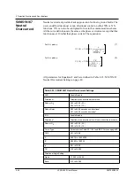
50N/67F element can be set to either forward directional or non-directional
when selecting the action, “ProLogic Only”.
If the pickup delay setting (Tp) < 9 ms, then 9 ms will be used for the delay.
Otherwise Tp will be used for the delay. This change is always applied regard-
less of the direction setting (Non-dir, FWD, REV) and the 3
I0
pickup level.
Note: If the directional element cannot determine a valid direction, the direc-
tion is set to “forward”, the 50N/67F may operate, and the 50N/67R element is
blocked. See “Directional Element” on page 4-10.
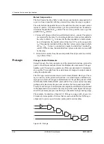
Basic Logic
The basic selection does not provide any communication-aided logic for local
or remote protections.
Figure 4.27: Communication-aided Scheme
PUTT SCHEME
DCB SCHEME
WEAK INFEED LOGIC
113
111
(If DCB shceme is
selected, Zone 4 must
be set reverse)
0
TWD3
3ms
TWD2
POTT SCHEME
118
117
102
104
105
106
108
110
114
6ms
TWD1
TL2
0
103
0
TD2
107
Receiver #1
Receiver #2
112
20ms
0
60
27 V1
59 V0
120
Receiver #1
Receiver #2
(+)
51N Alarm
50N-67F
21P2
21N2
50N-67R
101
TL1
TD1
116
21-4 R
21-2
21-2
119
115
Weak Infeed Enable
Switch
Receiver #1
Receiver #2
(+)
POTT
BASIC
SCHEME SELECTOR
PUTT
TL3, TD3 range: 0-1s
DCB
TL3
TD3
POTT
BASIC
PUTT
DCB
121
3I0 > Pickup
Forward
(+)
Non-directional
TCS
0
122
3I0 > Pickup
Reverse
TCB
0
21N4
21P4
21N2
21P2
21N1
21P1
Trip
Send
Summary of Contents for L-PRO 4000
Page 1: ...L PRO 4000 Transmission Line Protection Relay User Manual Version 2 3 Rev 0...
Page 2: ......
Page 4: ......
Page 8: ......
Page 10: ......
Page 14: ......
Page 40: ......
Page 50: ......
Page 116: ......
Page 146: ......
Page 218: ......
Page 252: ...Appendix B IED Settings and Ranges Appendix B 34 L PRO 4000 User Manual D02706R02 30...
Page 260: ......
Page 270: ......
Page 302: ......
Page 308: ......
Page 310: ......
Page 312: ......


