4 Protection Functions and Specifications
4-44
L-PRO 4000 User Manual
D02706R02.30
Mutual Compensation
The fault locator has the ability to take into account mutual compensation for
up to two lines in parallel with the protected line where the relay is applied.
The currents from the parallel line (s) is brought into the relay via spare current
inputs
I
A3
and
I
A4
. The currents from up to two parallel lines can be added to
determine the parallel line 3
I0
current. There are two possible ways to get the
parallel line 3
I0
currents.
1. Connect all 3 phases of the first parallel line into the
I
A3
inputs. The currents
are recorded by the relay if a recording initiation occurs and are added by
the relay to obtain 3
I
01
to be used in the line impedance to fault calcula-
tion. Alternatively, the neutral current from line 1 CTs can be connected to
I
A3
. This quantity is added with the other line 1 phase current inputs (which
are
I
B3
=
I
C3
= 0 since no connection is made) to obtain line 1 residual 3
I0
current. If this is done, the individual line 1 phase currents is not recorded
by the relay.
2. Connect the currents from the second parallel line (if present) in a similar
way to that of line 1.
ProLogic
ProLogic Control Statements
Using ProLogic, the relay can pick any of the protection functions, external in-
puts or virtual inputs and place them into Boolean-like statements. ProLogic
handles up to 5 functions to generate one ProLogic statement; 24 statements
are possible. The results from these statements are mapped to output contacts
using the output matrix.
The ProLogic control statements are used to create Boolean-like logic. The re-
lay can use any of the protection functions or external inputs combined with
logic gates to create a ProLogic control statement. The possible gates are AND,
NAND, OR, NOR, XOR, NXOR, and LATCH. The control can be time delay
pickup and or time delay dropout, and can drive the front panel target LED.
Twenty-four ProLogic control statements outputs are available and can be used
in the output matrix to customize the relay to specific needs. Inputs to ProLogic
are all the elements plus previous ProLogic statements for logic nesting usage.
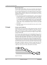
The example, for details see Figure 4.24: ProLogic on page 4-44, shows A to
E inputs are status points of devices that are user-selectable. Each ProLogic
output can be given a specific name, pickup and reset time delay.
Figure 4.24: ProLogic
T
O
A
B
C
D
E
Op 1
Op 2
Op 3
Op 4
Op 5
Summary of Contents for L-PRO 4000
Page 1: ...L PRO 4000 Transmission Line Protection Relay User Manual Version 2 3 Rev 0...
Page 2: ......
Page 4: ......
Page 8: ......
Page 10: ......
Page 14: ......
Page 40: ......
Page 50: ......
Page 116: ......
Page 146: ......
Page 218: ......
Page 252: ...Appendix B IED Settings and Ranges Appendix B 34 L PRO 4000 User Manual D02706R02 30...
Page 260: ......
Page 270: ......
Page 302: ......
Page 308: ......
Page 310: ......
Page 312: ......


