background image

EPSON Stylus COLOR C70/C80

Revision A

Adjustment

Adjustment

163

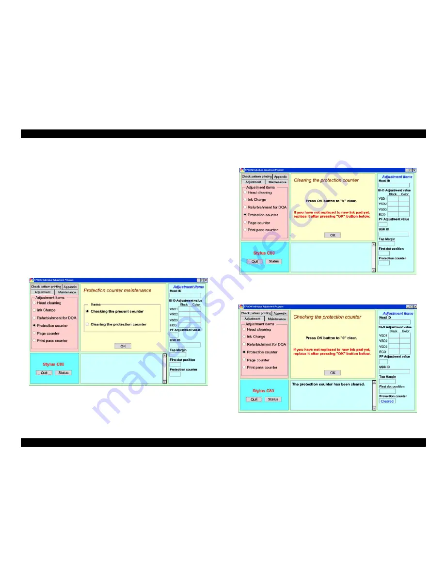
5.2.11  Protection Counter Clear (and Check)

This section describes how to clear the protection counter. This operation must be done 
under the following conditions.

1.

When replacing waste ink drain pad.

2.

When user carries on the unit that has been occurred the maintenance 
error.

3.

Refurbishment

1.

Replace to new waste ink drain pad by referring Chap 4 "Disassembly & Re-
assembly".

2.

Setup the adjustment program. Main screen (Figure 5-2) appears. 
(Refer to Section 5.2.1.)

3.

Select "Maintenance" and then "protection counter".

4.

Main screen changes as below.

Figure 5-50.  Protection Counter Operation Initial Screen

5.

Select "Clearing the protection counter", and press "O.K." button on the program 
screen.

Figure 5-51.  Protection Counter Clearing Screen

6.

Press "O.K." button on the program screen.

7.

Following screen appears.

Figure 5-52.  Protection Counter Clear Completion Screen

Summary of Contents for Stylus Color C70

Page 1: ...EPSONStylusColorC70 C80 Color Inkjet Printer SEIJ01 004 SERVICE MANUAL ...

Page 2: ... effort have been made to ensure the accuracy of the contents of this manual However should any errors be detected SEIKO EPSON would greatly appreciate being informed of them The above not withstanding SEIKO EPSON CORPORATION can assume no responsibility for any errors in this manual or the consequences thereof EPSON is a registered trademark of SEIKO EPSON CORPORATION General Notice Other product...

Page 3: ...E MUST BE CONNECTED USE EXTREME CAUTION IN WORKING ON POWER SUPPLY AND OTHER ELECTRONIC COMPONENTS 4 WHEN DISASSEMBLING OR ASSEMBLING A PRODUCT MAKE SURE TO WEAR GLOVES TO AVOID INJURIER FROM METAL PARTS WITH SHARP EDGES WARNING 1 REPAIRS ON EPSON PRODUCT SHOULD BE PERFORMED ONLY BY AN EPSON CERTIFIED REPAIR TECHNICIAN 2 MAKE CERTAIN THAT THE SOURCE VOLTAGES IS THE SAME AS THE RATED VOLTAGE LISTED...

Page 4: ...mponents layout Electrical circuit boards schematics Exploded diagram Parts List Symbols Used in this Manual Various symbols are used throughout this manual either to provide additional information on a specific topic or to warn of possible danger present during a procedure or an action Be aware of all symbols when they are used and always read NOTE CAUTION or WARNING messages Indicates an operati...

Page 5: ...Revision Status Revision Issued Date Description A July 31 2001 First Release ...

Page 6: ...ches 24 1 4 2 2 Indicators 24 1 4 3 Panel Functions 25 1 4 4 Printer Condition and Panel Status 26 1 4 5 Printer setting mode Stylus COLOR C80 only 27 1 4 5 1 Default setting mode 27 1 4 5 2 Print head alignment mode 28 1 4 6 Printer Initialization 28 1 4 7 Errors 29 1 5 PAPER 30 1 5 1 Paper Handling 30 1 5 2 Paper Specification 30 1 5 2 1 Cut Sheet 30 1 5 2 2 Envelope 30 1 5 2 3 Index Card 30 1 5...

Page 7: ...Handling Failure 93 3 1 6 10 ASF Driver Abnormal 2 93 3 1 6 11 CR Motor Operation Abnormal 95 Chapter 4 Disassembly and Assembly 4 1 Overview 97 4 1 1 Precautions 97 4 1 2 Tools 98 4 1 3 Work Completion Check 99 4 1 4 Screws 100 4 2 Disassembly 101 4 2 1 Housing Removal 102 4 2 1 1 Printer Cover Removal 102 4 2 1 2 Stacker Assembly Removal 102 4 2 1 3 Upper Case Removal 103 4 2 1 4 Rear Cover Remo...

Page 8: ...nter Clear and Check 163 5 2 12 Top Margin Adjustment 164 5 2 13 First Dot Position Adjustment 166 Chapter 6 Maintenance 6 1 Overview 170 6 1 1 Cleaning 170 6 1 2 Service Maintenance 171 6 1 3 Lubrication and Adhesion 172 6 1 4 Lubrication the Carriage Guide Shaft 173 Chapter 7 Appendix 7 1 Connector Summary 183 7 1 1 Major Component Unit 183 7 1 2 EEPROM Address Map 187 7 1 3 CSIC Address Map 193...

Page 9: ...C H A P T E R 1 PRODUCTDESCRIPTION ...

Page 10: ...der Holds 150 cut sheets 64g m2 Holds 15 envelopes Built in 2 I F Bi directional parallel I F IEEE 1284 level 1 device USB Windows Macintosh exclusive Stylus COLOR C70 only 1 scalable fonts 2 LQ fonts Stylus COLOR C80 only Roman scalable Roman Courier LQ Accessory Enclosed parts User s manual 1 Driver disk 1 Black ink cartridge 1 Cyan ink cartridge 1 Magenta ink cartridge 1 Yellow ink cartridge 1 ...

Page 11: ...bles Stylus COLOR C70 2 international character sets PC 437 US Standard Europe PC 850 Multilingual NOTE But user cannot selsct PC437 is the default setting Table 1 1 Character Mode Stylus COLOR C70 Character Pitch Printable Columns LQ Speed 10 CPI Pica 80 238 CPS Paper Ejecting Direction Table 1 2 Character Mode Stylus COLOR C80 Character Pitch Printable Column LQ Speed 10 CPI Pica 80 238 CPS 12 C...

Page 12: ...C80 only NOTE Do not describe in manual These character tables can t select in the Default setting mode Table 1 4 Character table and Typeface Character table Bit map font Scalable font EPSON Roman EPSON Courier EPSON Roman DOS version Italic table PC 437 US Standard Europe PC 850 Multilingual PC 860 Portuguese PC 861 Icelandic PC 865 Nordic BRASCII Abicomp Roman 8 ISO Latin 1 PC 858 ISO 8859 15 s...

Page 13: ...5Hz Rated Current 0 6A max 1 2A Power Consumption Approx T B D ISO 10561 Letter Pattern Approx 5W in standby mode Energy Star compliant Insulation Resistance 10 M ohms min between AC line and chassis DC 500V Dielectric Strength AC 1000V rms 1 minute or AC 1200V rms 1second between AC line and chassis 220 240V Version Rated Voltage AC220V 240V Input Voltage Range AC198 264V Rated Frequency Range 50...

Page 14: ...Condition is as following figure Figure 1 2 Temperature Humidity Range 1 2 7 Reliability Total Print Volume 75 000 pages A4 Letter Print Head Life 3000 million dots nozzle 1 2 8 Safety Approvals 120V Version Safety Standards UL1950 CSA 22 2 No 950 EMI FCC part 15 subpart B Class B CSA C108 8 Class B 220 240V Version Safety Standards EN60950 VDE EMI EN55022 CISPR Pub 22 Class B AS NZS 3548 Class B ...

Page 15: ...ng When input data buffer is full During INIT signal is at low level or during hardware initialization During printer error see ERROR signal When the parallel interface is not selected ERROR signal is at low level when the printer is in one of the following states Printer hardware error fatal error Paper out error Paper jam error Ink out error Maintenance request Double feed PE signal is at high l...

Page 16: ...ctively Each signal is at high level when data is logical 1 and low level when data is logical 0 3 DATA 1 21 In 4 DATA 2 22 In The DATA 0 through DATA 7 signals represent data bits 0 to 7 respectively Each signal is at high level when data is logical 1 and low level when data is logical 0 5 DATA 3 23 In 6 DATA 4 24 In 7 DATA 5 25 In 8 DATA 6 26 In 9 DATA 7 27 In 10 ACKNLG 28 Out This signal is a n...

Page 17: ...hese signals are used to transfer the 1284 extensibility request values to the printer 3 DATA 1 21 In 4 DATA 2 22 In 5 DATA 3 23 In 6 DATA 4 24 In 7 DATA 5 25 In 8 DATA 6 26 In 9 DATA 7 27 In 10 PtrClk 28 Out Printer clock signal 11 PtrBusy DataBit 3 7 29 Out Printer busy signal and reverse channel transfer data bit 3 or 7 12 AckDataReq DataBit 2 6 28 Out Acknowledge data request signal and revers...

Page 18: ... When IEEE1284 4 is disabled 00H 4BH MFG EPSON CMD ESCPL2 BDC MDL STYLUS SP COLOR SP C70 C80 CLS PRINTER DES EPSON SP STYLUS SP COLOR SP C70 C80 1 3 3 USB Interface Standard Based on Universal Serial Bus Specifications Revision 1 0 Universal Serial Bus Device Class Definition for Printing Devices Version 1 0 Bit Rate 12 M bps Full Speed Device Data Encoding NRZI Adaptable Connector USB Series B Re...

Page 19: ...nges to other Interface are prohibited during Duplex printing Interface State and Interface Selection When the parallel interface is not selected the interface got into the busy state When the printer is initialized or returned to the idle state the parallel interface got into the ready state Caution that the interrupt signal such as the INIT signal on the parallel interface is not effective while...

Page 20: ...om Margin ESC C ESC C ESC C0 ESC S ESC Q ESC I ESC c ESC N ESC O Print position motion Horizontal Print Position Vertical Print Position Tab Horizontally Tab Vertically Advance paper ESC ESC ESC V ESC v ESC D HT ESC B VT ESC J Font selection Typeface Pitch and Point Pitch Italic font Bold Font Master Select ESC k ESC x ESC X ESC P ESC M ESC g ESC p ESC 4 ESC 5 ESC E ESC F ESC Font enhancement Doub...

Page 21: ... ESC ESC ESC V ESC v Spacing Define Unit ESC U Graphics Graphics Mode Raster Graphics Dot size control Print a Image Microweave control Stylus COLOR C80 ESC G ESC ESC D ESC i ESC e ESC ACK ESC i Printing mode Printing mode ESC K Color Printing Color ESC r ESC r Table 1 14 Command List Contents Command m1 Reply Device ID di Reply Status string st Reply Cartridge Position cx Reply Ink Cartridge cond...

Page 22: ...es The parameter Status Code is two bytes of ASCII codes that indicates printer status Error Codes The parameter Error Code is two bytes of ASCII codes that indicates following errors of a printer Parameter Mean Note m1 m2 year year m2 x 256 m1 m3 month 1 m3 12 m4 day 1 m4 31 m5 hour 0 m5 24 m6 minute 0 m6 60 m7 second 0 m7 60 Table 1 15 Status Codes Status Status code Priority Error 00 1 Self tes...

Page 23: ...tion The parameter KK CC MM YY are two bytes ASCII codes that indicate ink weight rank ID of black ink Cyan ink magenta ink and yellow ink respectively The parameter mm is two bytes ASCII codes that indicate Select Microweave ID to determine the feed length of Microweave printings Cleaning time information The parameter TTTT is four bytes ASCII codes that indicate total time of cleaning or chargin...

Page 24: ...s There are 2 non lock type push switches 1 lock type push switch and 3 LED Figure 1 5 Control Panel 1 4 2 2 Indicators 1 Power Lights when the operate switch is ON and AC power is supplied 2 Paper Out Lights during the paper out condition and blinks during the paper jam condition 3 Ink Out Lights during no ink condition and blinks during the ink low condition Ink Button Paper Button Power Button ...

Page 25: ...k change position return carriage from ink cartridge change position Cleaning Pushing for 2 seconds 1 Starts the cleaning of head In the condition of Ink Low or Ink Out or No Ink Cartridge starts the ink cartridge change sequence 2 Table 1 19 Panel Functions with Power On Stylus COLOR C70 Switch Pressing with Power on Function Load Eject Start status printings 1 Load Eject Cleaning Enters the part...

Page 26: ...rinted and so double feed and paper out errors are handled in the same way This is considered to be a refinement of conventional paper jam detection Table 1 23 Particular settings mode Stylus COLOR C70 Switch Function Load Eject Initialize EEPROM 3 Cleaning Pushing for 10 seconds Reset the ink overflow counter in EEPROM 3 Table 1 24 Particular settings mode Stylus COLOR C80 Switch Function Paper I...

Page 27: ... button is pressed and the combination of those three LEDs status of On Off Blink 2 Blinks will be changed according to the selection e When Load Eject button is pressed Printer changes the indication to the setting value of the selected menu Paper Out LED Ink Out LED and Power LED show the current setting value f Select setting value by Load Eject button Paper Out LED Ink Out LED and Power LED sh...

Page 28: ... as many times as needed to properly align all the test patterns on the printouts i Turn the printer off 1 4 6 Printer Initialization There are three kinds of initialization method 1 Power on Initialization This printer is initialized when turning the printer power on or printer recognized the cold reset command remote RS command When printer is initialized following action is performed a Initiali...

Page 29: ...k level detection and may cause a serious problem in the print head as a result Paper Out When printer fails to load a sheet it goes paper out error Paper Jam When printer fails to eject a sheet it goes a paper jam error No Ink Cartridge When printer detects that ink cartridge comes off it goes this error mode Maintenance Request When the total quantity of ink wasted through the cleanings and flus...

Page 30: ...h 356 mm Statement Width 139 7 mm x Length 215 9 mm Executive Width 184 2 mm x Length 266 7 mm Photo Paper Width 101 6 mm x Length 152 4 mm Thickness 0 08mm 0 11mm Weight 64g m2 17 lb 90g m2 24 lb Quality Exclusive paper Bond paper PPC Table 1 28 Paper Specification Envelope Size No 10 Width 241 mm x Length 104 8 mm DL Width 220 mm x Length 110 mm C6 Width 162 mm x Length 114 mm Thickness 0 16mm 0...

Page 31: ... x Length 297 mm Letter Width 215 9 mm x Length 279 4 mm Thickness 0 23 mm Weight 167 g m2 44 lb Table 1 33 Archival Matte Paper Size A4 Width 210 mm x Length 297 mm Letter Width 215 9 mm x Length 279 4 mm Thickness 0 25 mm Weight 189 g m2 50 lb Table 1 34 Premium Glossy Photo Paper Size A4 Width 210 mm x Length 297 mm Letter Width 215 9 mm x Length 279 4 mm Thickness 0 27 mm Weight 255 g m2 68 lb...

Page 32: ...A4 3 mm 0 12 3 mm 0 12 3 mm 0 12 14 mm 0 54 Letter 3 mm 0 12 9 mm 0 35 3 mm 0 12 14 mm 0 54 B5 3 mm 0 12 3 mm 0 12 3 mm 0 12 14 mm 0 54 Legal 3 mm 0 12 9 mm 0 35 3 mm 0 12 14 mm 0 54 Statement 3 mm 0 12 3 mm 0 12 3 mm 0 12 14 mm 0 54 Exclusive 3 mm 0 12 3 mm 0 12 3 mm 0 12 14 mm 0 54 Table 1 40 Raster Graphics mode Paper Size Left margin min Right Margin min Top Margin min Bottom Margin min A4 3 m...

Page 33: ... 7 Printable Area for Envelopes Table 1 41 Envelope Margin Paper Size Left Margin min Right Margin min Top Margin min Bottom Margin min 10 3 mm 0 12 28 mm 1 10 3 mm 0 12 14 mm 0 55 DL 3 mm 0 12 7 mm 0 28 3 mm 0 12 14 mm 0 55 C6 3 mm 0 12 3 mm 0 12 3 mm 0 12 14 mm 0 55 Printable Area LM RM TM BM ...

Page 34: ...ge 1 6 2 Color Ink Cartridge Type Exclusive Cartridge Color Magenta Cyan Yellow Print Capacity 420 pages A4 360 dpi 5 duty each color Ink Life 2 years from production date Storage Temperature 20 oC to 40 oC Storage within a month at 40 oC 30 oC to 40 oC Packing storage within a month at 40 oC 30 oC to 60 oC Transit within 120 hours at 60 oC and within a month at 40 oC Dimension 12 7 mm W x 71 2 mm...

Page 35: ...C H A P T E R 2 OPERATINGPRINCIPLES ...

Page 36: ... This printer consists of Print Head Carriage Mechanism Paper Feeding Mechanism Paper Loading Mechanism Ink System Pump Mechanism Cap Mechanism and Carriage Lock Mechanism Like other EPSON ink jet printers the Stylus COLOR C70 C80 is equipped with two DC motors one for ASF Paper feeding Pump mechanism and one for CR mechanism ASF unit uses rear entry front eject system This ASF unit is also design...

Page 37: ...nk cartridge goes through the filter and then is stored temporarily in this tank called cavity until PZT is driven Nozzle Plate The board with nozzle holes on the printhead surface is called Nozzle Plate Electrodes for CSIC chip The communication between CSIC chip and main unit is performing via the electrodes on the carriage Filter When the ink cartridge is installed if any dirt or dust around th...

Page 38: ...he media and the resolution setting of the printer driver The following explains each printing mode Normal dot printing With this printer Economy dot printing is basically used only during Economy mode printing The reason is that the resolution is low during Economy mode printing so that the dot size needs to be bigger Economy printing consists of 2 shots Variable dot printing This printing mode i...

Page 39: ...transferred to the CR unit via CR timing belt And the CR home position is detected when firmware judges the carriage is going out of step at right side Previous products this printer have the PG adjustment value 1 35mm The PG lever selections that can be carried out by the customer are shown in the following table Figure 2 4 Carriage Mechanism Top view CR home position is detected by the feed back...

Page 40: ...n cleaning will start Table 2 2 PF Motor Specifications Figure 2 6 Paper Feeding Mechanism Paper loaded from ASF is advanced by the following roller Paper feed roller Paper guide roller assembled on the Top Frame Paper eject roller Star wheel roller assembled on the Paper eject frame Additionally the top end of the paper is detected with the PE sensor In case the PE sensor dose not detect the pape...

Page 41: ...ult is that this key shape encourages the customer to remove the excess number of sheets and to place them back into the hopper 2 Another purpose of the ASF support guide is that when the paper back lever snaps back into place during paper feeding the paper back lever also brings the key shaped ASF support guide back to prevent multiple sheets of paper from being fed at once thus improving the rel...

Page 42: ... to the left side of the printer and contacts the Change lever causing the hook of the Change lever to disengage from the projection on the Clutch Figure 2 8 Paper feeding 1 3 The driving force from the PF motor is transmitted via Combination gears 18 4 and 32 8 Spur gear 22 4 Spur gear 12 and Combination gear ratchet 33 4 in that order causing the clutch and the LD roller to rotate clockwise so t...

Page 43: ...s the change lever from returning Figure 2 10 Standby condition 1 3 The driving force from the PF motor is transmitted via combination gears 18 4 and 32 8 spur gear 22 4 the planetary gear set spur gear 12 and the clutch body in that order causing the clutch and the LD roller to rotate counterclockwise Figure 2 11 Standby condition 2 4 The hopper is moved back so that 150 sheets of paper can be lo...

Page 44: ... 14 Silence Cam mechanism 1 Figure 2 15 Silence Cam mechanism 2 C H E C K P O I N T The silence cam and the silence lever on the ASF right frame apply a large amount of torque from A to B in order to move the hopper back to the standby mode position Figure 2 12 Standby condition 3 During paper feeding the LD roller is only rotated by combination gear ratchet 34 4 but in standby mode the planetary ...

Page 45: ...hen the top of the slow down nail reaches at top of the red row in Figure 2 16 hopper has already been located in hopping state and a first paper has already been loaded to the printer internal 6 Figure 2 17 shows the hopper condition when the top of slow dawn nail locates at top of red row in Figure 2 16 At this time any clatter noise will not be occurred caused by the shape of silence cam 6 1 Ho...

Page 46: ...lence CAM The jumped out paper return lever is the same condition to Step 4 10 After the Step 9 operation completes once loaded paper will more be loaded and ejected by the friction between PF roller and PF support rollers without ASF operation Figure 2 19 Silence Cam mechanism 6 C H E C K P O I N T But the stand by position Step 8 says does not mean the initial hopper status which Step 1 shows An...

Page 47: ... a 1st paper silence cam will rotate to counter clockwise direction and will soon change its direction to clockwise direction to make the ASF return to its stand by condition shown No 1 After completing this reset operation user can install more enough papers from the front side of the current installed papers maximum 150 sheets of normal plain papers Because the hopper status is in the same condi...

Page 48: ...gear 28 8 for driving LD roller on ASF 14 When the silence cam rotates to counter clockwise the cam gear will rotate to clockwise And a part of circle arc cam on the cam gear pushes down the paper return transmission lever And paper return lever will be laid to guide a top paper to the printer internal Figure 2 21 Silence Cam mechanism 9 C H E C K P O I N T There are two alignments on the right si...

Page 49: ...eding mechanism and pump unit through the following gears Refer to the Figure 2 23 The Pump unit and Wiper mechanism drives according to the PF motor rotational direction as shown in the right table Table 2 3 PF motor rotational direction Ink System Mechanism 1 The PF Motor rotational direction seen from the right side of the printer Following figure shows the overview of the pump mechanism operat...

Page 50: ... the Air valve the negative pressure is decreased and only the ink inside the cap is ejected the ink is not absorbed from Ink cartridge or head cavity But valveless cap system this operation is done out side of the capping area The CR moves to left side of the Cap assembly and the pump absorbs the ink inside the cap 1 Due to rationalization there is no sponge inside the cap 2 Previously the sponge...

Page 51: ...tage is described below Table 2 4 Application of the DC Voltages AC voltage input from AC inlet first goes through filter circuit that removes high frequency components and is then converted to DC voltage via the rectifier circuit and the smoothing circuit DC voltage is then lead to the switching circuit and FET Q1 preforms the switching operation By the switching operation of the primary circuit ...

Page 52: ...t the point that this voltage drops at the certain voltage C13 absorbs the current in the opposite direction and Q1 is quickly shut off by the resulting sharp drop 6 When the primary side is turned off the energy charged in the T1 is opened according to the diode D51 direction which is installed on the secondary side Basically 42 V DC is output by these circuit operations and the number of T1 spir...

Page 53: ... 42V line forcefully when the voltage level drops to 36V 42VDC line over voltage circuit This circuit is in the same line as 5V line over voltage protection circuit is located The output level is monitored by two Zener diodes ZD52 87 If the voltage level exceeds 48VDC this circuit shuts down the 42V line forcefully 5V line control circuit The output current is monitored by the 5VDC generation swit...

Page 54: ...erform the Power on cleaning or Timer cleaning based on the time command which is sent from the printer driver On the other hands Stylus C80 has a timer circuit in IC6 This IC6 is the hybrid IC including EEPROM Reset circuit and timer circuit Also this IC6 has a big capacity capasitor inside IC Insted of previous lithium battery DRAM 4Mbit for the Stylus C70 and 16Mbit for the Stylus C80 DRAMS are...

Page 55: ...en 2 5V is detected For 5V reset when 4 2V is detected For 42V reset when 36 7V is detected Common Pre Driver IC13 Head drive control HIC Generates head common voltage Motor Driver IC8 CR PF motor drive IC Parallel I F IC IC4 IEEE1284 parallel I F transceiver IC IC Location Function CPU ASIC 2 in 1 E01A27CA IC7 8KB CPU mounted on the MAIN board is driven by clock frequency 24MHz and controls the p...

Page 56: ...gles is selected Then setting the selected data producing trapezoid waveform value and canceling the data are performed by the rising edges of the CLK1 and CLK2 signals Head nozzle selector circuit Printing data is converted into serial data by the CPU IC7 Then the converted data is allocated to the six rows the number of the head nozzle rows to be transferred to the nozzle selector through the se...

Page 57: ...Stylus COLOR C80 Reset circuits are mounted on the MAIN board to monitor the two voltages 5V for the logic line and 42V for the drive line When each circuit detects abnormality on the corresponding line it outputs a reset signal to reset CPU IC7 This function is necessary to prevent the printer from operating abnormally This IC monitors both 5V and 45 lines but can reset them independently The res...

Page 58: ...or uses photo interrupter method and detects the following two status The photo interrupt component and two detection levers consists of this sensor Paper Top End position When the Paper is in the paper path this sensor outputs the HIGH signal When the Paper is not in the paper path this sensor outputs the LOW signal This status is always monitored during the printer is in the power on status with...

Page 59: ...uit Operating Principles 59 Figure 2 32 PE Sensor Circuit Diagram Head Around Temperature IC7 E01A27CA HLAT HCH HNCHG HSOCLK HSOCMD2 HSOCMD1 C_P41 C_P42 SWA1 51 50 52 48 46 47 56 57 178 14 8 16 6 2 4 12 10 LAT CH NCHG SCK SI2 SI1 AND1 AND2 CN9 Head FFC P1 PE Sensor 3 3V 3 3V ...

Page 60: ...C H A P T E R 3 TROUBLESHOOTING ...

Page 61: ...ith your other hand as the chance of receiving an electric shock at such times is extremely high C H E C K P O I N T Disassembly and reassembly of parts is often required when identifying the causes of problems The parts should be disassembled and re assembled correctly while referring to Chapter 4 Disassembly and Assembly so that the operation and status of each check item can be correctly verifi...

Page 62: ...stment software to rewrite the setting to the default 00H The relationship between the interface protocol setting status and the setting values is given below For details refer to Chapter 5 NOTE The Stylus COLOR C80 has a default setting function but unlike previous models interface protocol selection is not possible Furthermore the Stylus COLOR C70 does not have its own default setting function E...

Page 63: ...h possibility that the various adjustment values may be distorted Because of this all parameter electrical adjustments should be carried out afresh Refer to Chapter 5 for details 2 Use the adjustment program to check the 65H address IEEE 1284 4 for USB for the EEPROM The relationship between the IEEE 1284 4 for Parallel setting status and the setting values is given below 00H Auto Status cannot be...

Page 64: ...f paper lodged in between a paper load sub roller and the PF roller 4 The bushing at the left of the PF roller is dislodged from the mechanism and is not rotating smoothly 5 The powder coating on the PF roller shaft is extremely dirty or has sections that are missing powder 6 The EJ roller holder is not secured to the paper eject roller shaft and is loose 7 The bushings 5 are not securing both end...

Page 65: ...s if it can go in further 5 Connector CN8 on the main board is disconnected or nearly disconnected 6 A heat hot error has occurred 7 The actual amount of ink remaining and the remaining ink data recorded in the CSIC EEPROM are mismatched as a result of a refilling operation 8 The data in the CSIC EEPROM is corrupted 5 Ink Low Indication Refer to Section 3 1 4 3 No error status is indicated but an ...

Page 66: ...in the paper running out before the last page or the last few pages are printed and so double feed and paper out errors are handled in the same way This is considered to be a refinement of conventional paper jam detection Be sure to follow the steps in the order described in the tables NOTE If the finding for the question is Yes take the action described in the right column If No proceed to the ne...

Page 67: ... 6 Communication Error Checking Point Step Check Point Remedy Slip of paper or foreign substance Correct Location Busing for PF Roller Shaft Many Paper Powders or a Big Scratch Marks on the PF Roller Shaft 6 Is the EJ roller holder not secured to the paper eject roller shaft and is it loose Place the EJ roller holder in the correct position 7 Has the bushing 5 that secures the paper eject roller s...

Page 68: ...paper feed and paper eject timing correctly If the tension spring for the PE lever has come off reinstall it while referring to the illustration below Table 3 6 Communication Error Checking Point Step Check Point Remedy Actuator for PE Sensor PE Sensor Photo Coupler Type Torsion Spring PE Lever PE Lever Base 12 Has one of the grounding wires become disconnected and is blocking the paper path Check...

Page 69: ...e or does it look to be okay but when you try to push it in does it feel as if it is slightly loose CN1 is the connector that handles the input and output of signals between the main board and the mechanism It inputs the various encoder signals to the main board from the mechanism and outputs head drive signals from the main board 16 During paper back ASF reverse drive operation does the paper bac...

Page 70: ...t checking the PE sensor should be carried out by replacing the circuit board and checking the operation At this time the head ID only should first be input to the EEPROM on the main board so that a head hot error does not occur No other adjustments are required when carrying out checking Table 3 6 Communication Error Checking Point Step Check Point Remedy Paper Return Lever Tension Spring Check P...

Page 71: ...f the problem can be assumed to be the reason given at left If this does not solve the problem proceed to the next step NOTE This printer has sus plates installed to the carriage in order to assist with securing and removal of the ink cartridges The heights of the sus plates that apply tension to each color ink cartridge can be changed in order to alert the customer to the fact that the cartridges...

Page 72: ...en an ink out cartridge out error is displayed even though a brand new ink cartridge has been installed Step Check Point Remedy Correct Situation Incorrect Situation Dislocated IC Chip Electrodes 6 Is the FFC disconnected from connector CN1 on the circuit board underneath the carriage or does it look to be okay but when you try to push it in does it feel as if it is slightly loose CN1 is the conne...

Page 73: ...oblem returns to normal If it does return to normal the head hot error is probably the fault of the customer The approach to head hot errors has changed from the Stylus COLOR 900 980 so that with this printer there is no way to check the history of whether head hot errors have occurred or not by checking the specified address in the EEPROM The differences in heat hot errors between this printer an...

Page 74: ...he data was recorded incorrectly when the CSIC chip was shipped from the factory data is randomly corrupted 1 2 The CSIC chip was shipped without being initialized for some reason 1 3 The hand of the customer touched the chip while charged with static electricity and this caused the data in the EEPROM to be randomized so that the data became corrupted 2 A head hot error as described in No 7 occurr...

Page 75: ...and new ink cartridges by the following procedure Step1 The customer presses the replace button to move the carriage to the replacement position Step2 The customer removes the cartridge which is currently showing an Ink Low or Ink Out status If a cartridge showing an Ink Out status is removed at this time the Ink Out indication does not change If a cartridge showing an Ink Low status is removed th...

Page 76: ...factory default from 4 I F selection items Auto Parallel Serial and Option 3 1 4 5 Remedies for Fatal Error Fatal errors can occur with this printer for one of the following two reasons When the status of the signal from the sensor to the main board indicates that there is a problem with the carriage motor operation and status When the status of the signal from the sensor to the main board indicat...

Page 77: ...iner Scale Dust or Smeared Points 2 Is the FFC disconnected or almost disconnected from the junction board on the underside of the carriage CN1 is the connector that handles the input and output of signals between the main board and the mechanism It inputs the various encoder signals to the main board from the mechanism and outputs head drive signals from the main board 3 Is the rotary scale not m...

Page 78: ...Resistance value 23 3 ohms 15 DC NOTE Look carefully at the whole of the coverings of the two harnesses and make sure that there are no holes anywhere in the coverings If a hole is found anywhere measure the internal coil resistance and replace just the harness if the resistance value is normal However none of the harnesses for the spare parts motors are supplied as single parts 8 Is there a malfu...

Page 79: ...y Table 3 10 Countermeasures when a fatal error occurs Step Check Point Remedy W A R N I N G Be careful to avoid electric shocks when checking the electrical circuit boards C424 MAIN B PSE and B circuit boards while the power is turned on When touching parts such as the FETs or the surface of the heat sink on the transistor with one hand never touch other metallic parts of the mechanism with your ...

Page 80: ... head are normal Furthermore when checking the print head side check that there are no burn residues on the head driver board 3 If the check in No 2 above indicates a problem at either end replace the main board the power supply board the print head and whichever motor showed a problem Furthermore if no problems were found there is probably a problem with the main board and so the main board and p...

Page 81: ...n 6 pin 7 Negative tester probe Either pin 3 pin 4 or pin 8 Table 3 11 Isolating the Faulty Part on the Power Supply Board Step Check Point Remedy 6 pin 2 pin 1 pin 7 pin 42VDC 1 2 pin 5VDC 6 7 pin 8 Even though the power supply board is supplying a normal voltage is the 3 3 V DC power supply voltage that is used to control the main board normal Check whether the 5 V DC power supply voltage at IC9...

Page 82: ...ge Out Error Dot dropout appears to be happening a lot and then suddenly an Ink Out indication appears However the ink cartridges are almost new or are still quite full Refer to Section 3 1 6 3 4 PF Motor Driver Abnormal 2 Noise occurs around the PF motor each time the PF motor operates Refer to Section 3 1 6 4 5 Carriage Operation Abnormal When the power is turned on the carriage appears to move ...

Page 83: ...the rotary scale not moving in between the PF encoder photo coupler parts or is there a problem around the photo sensor If the rotary scale is not inside the photo sensor a fatal error will occur Check if the condition is as shown in the illustration below or not If the rotary scale is not inside the photo sensor re adjust the rotary scale so that it is inside the photo sensor Furthermore check if...

Page 84: ... left side frame correctly visible from the cut away part of the mechanism If it is not protruding it needs to be reset Cutting Part Carriage Motor ASF Change Lever CR Motor Left Side of the Printer Mechanism Protrusion 1 Front View PF Motor Protrusion 2 Bottom View 1 Cont Is the ASF installed correctly to the printer mechanism 3 The PF motor harness routed correctly If the harness is routed incor...

Page 85: ...this abnormal condition was detected causing the following sequence to occur 1 Abnormal temperature is detected At this time the actual temperature inside the head is approximately 100 C 2 Printing of the current character data is momentarily stopped 3 After this cleaning CL1 starts automatically 4 Printing of the current character data resumes If no abnormal temperature is detected after this and...

Page 86: ... the belt tension cannot be checked to see if it is normal just by touching it reset the belt tension by the following procedure 1 Remove the tension spring that is attached to the screw securing the PF motor 2 Loosen the two screws that are securing the PF motor They do not need to be removed 3 Remove the timing belt from the pinion gear 4 Set the timing belt onto the pinion gear 5 Attach the ten...

Page 87: ...ed from the mechanism so first check the hooks of the PG lever and make sure that they are securely fastened 2 Is the right end of the carriage guide shaft also attached correctly to the frame in the same way as above The photograph below shows the right end of the carriage guide shaft in its correct position The end of the shaft that is protruding from the frame is secured by means of the notch i...

Page 88: ...t correctly protruding from the notch in the EJ frame Cause 2 The EJ roller shaft is not correctly secured by bushing 5 or the PF motor drive is not being transmitted correctly Cause 3 The pump unit is not secured correctly to the frame and when the gear load increases the carriage lock lever cannot be operated In this case the EJ roller shaft also will not rotate Table 3 17 Carriage Operation Abn...

Page 89: ...strations below show connectors CN8 and CN9 which affect printing Be sure to disconnect the AC cable and then re seat it When re seating the cable press the FFCs by hand to see if they can be pushed in any further If they can then the FFC connections to CN8 and CN9 are probably loose even if they are not inserted at an angle If this is the case problems with printing will occur 2 Is the fuse F1 th...

Page 90: ...eat the cleaning process until they are fully clean If they do not appear to be returning to normal proceed to step 2 Furthermore the dummy cleaning operation that was used in older models is not supported by this model so there is no problem with carrying out cleaning operations repeatedly 2 Can the cap unit operate normally Press the part shown below by hand and check that it moves and that the ...

Page 91: ...t After carrying out all checks carry out cleaning once more and check if the problem is solved 4 Use the adjustment program to carry out forced cleaning CL3 and check if printing returns to normal Check that the mis firing nozzle s gradually return to normal If they do appear to be returning to normal repeat the CL3 cleaning procedure using the adjustment program until the nozzles are all fully c...

Page 92: ...sult in a head hot error but the voltages an frequency correction data that are appropriate for that head will not be stored on the main board and so the control carried out will not match the head s performance and unstable printing may result Refer to Chapter 5 for details 3 Has the head ben replaced If angle adjustment has not been carried out it should be carried out Refer to Chapter 5 for det...

Page 93: ...s COLOR C80 or C70 been installed by mistake because the boards have the same name The EEPROMs on each board contain the model name data When the power is turned on the model name data that is stored in the ROM and the EEPROM data are compared and checked and if the model name is incorrect the printer develops a fatal error Table 3 22 ASF Abnormal 2 Step Check Point Remedy 1 Does noise occur in th...

Page 94: ...pplies a load inside the planetary gear is too strong and the planetary gear cannot lift up Cause 2 The friction of the shafts that pass through the planetary gear set is to strong and the planetary gear cannot lift up Cause 3 The ASF change lever is not installed correctly so that even when the carriage contacts the change lever it does not move and so the clutch remains engaged Table 3 22 ASF Ab...

Page 95: ...se the coil inside the motor to seize To prevent this from happening the Stylus COLOR C70 C80 carries out the following controls 1 If continuous printing is carried out for 150 pages and printing continues past this the carriage drive speed does not change but a 3 second waiting time is introduced after each pass is completed This always occurs when the carriage moves from left to right or from ri...

Page 96: ...C H A P T E R 4 DISASSEMBLYANDASSEMBLY ...

Page 97: ...the appendix Read precautions described in the next section before starting 4 1 1 Precautions See the precautions given under the handling WARNING and CAUTION in the following column when disassembling or assembling the product W A R N I N G Disconnect the power cable before disassembling or assembling the printer If you need to work on the printer with power applied strictly follow the instructio...

Page 98: ... assembling if an ink cartridge is removed and needs to be installed again be sure to install a new ink cartridge because of the following reasons 1 Once the ink cartridge mounted on the printer is removed air comes in and creates bubbles in the cartridge These bubbles clog ink path and cause printing malfunction 2 If an ink cartridge in use is removed and is reinstalled ink quantity will not be d...

Page 99: ... Not too heated Checked Not necessary Paper Feeding Mechanism Is paper advanced smoothly No paper jamming No paper skew No multiple feeding No abnormal noise Checked Not necessary Is the PF Motor at correct temperature Checked Not necessary Is the paper path free of any obstructions Checked Not necessary Adjustment Specified Adjustment Are all the adjustment done correctly Checked Not necessary Lu...

Page 100: ...on Description C B P Cross recessed Binding Head P tite screw C B S Cross recessed Binding Head S tite screw C P Cross recessed Pan Head screw C B 0 Cross recessed Binding Head sems B type screw C C Cross recessed Cup Head screw Table 4 4 List of Screw Types No Specifications Appearance No Specifications Appearance 1 No 1 C B P M3x10 2 No 2 C B S M3x6 3 No 3 C B P M4x12 4 No 4 C B S M3x8 5 No 5 C ...

Page 101: ...0 P 125 4 2 7 P 121 4 2 8 P 122 4 2 6 P 116 4 2 11 P 126 4 2 10 1 P 125 Stacker Assembly Removal Upper Case Removal Rear Cover Removal Middle Housing Removal Printer Mechanism Removal Housing Removal ASF Unit Removal Main Board Assembly Removal PF Motor Removal CR Motor Removal ASF Unit Disassembling Cap Unit Removal PE Actuator Removal Encoder Unit Board Removal Paper Eject Frame Unit Removal Pri...

Page 102: ...l 4 2 1 2 Stacker Assembly Removal 1 Open the Stacker Assembly 2 Use a flat tipped screwdriver or similar tool to disengage the two Hooks and then remove the Stacker Assembly Figure 4 3 Stacker Assembly Removal C A U T I O N If you do not use a tool such as a flat tipped screwdriver to open a gap when removing the printer cover the hinges may strain and bend Be careful not to let this happen Be ca...

Page 103: ... Case Figure 4 4 Screws Securing the Upper Case 4 Use tweezers or a flat tipped screwdriver to disengage the front four Hooks of the six Hooks that are securing the Upper Case and also the Hook near the PG Lever at the left side of the printer Then lift up the right side of the Upper Cover while pivoting it on its left side and remove it from the printer Figure 4 5 Hooks Securing the Upper Case C ...

Page 104: ...er Figure 4 7 Hooks Securing the Rear Cover 4 2 1 5 Middle Housing Removal 1 Remove the Rear Cover Refer to Section 4 2 1 4 2 Remove the six screws 1 CBP 3x10 6 1 kgf cm that are securing the Middle Housing Figure 4 8 Screws Securing the Middle Housing 3 Disengage the Hook widen the Middle Housing at the front and back slightly while being careful not to pull the I F clamps and the USB connector a...

Page 105: ... Securing the Lower Case C H E C K P O I N T Use a flat tipped screwdriver or your finger to disengage the Hook from the notch at the bottom of the Lower Case C A U T I O N When removing the Middle Housing be careful no to let the screw fixing lip at the left of the printer come into contact with the PG Lever Tension Spring and cause it to fly off Be careful not to break the Middle Housing Hook Ho...

Page 106: ... Hooks W A R N I N G When you install the printer mechanism on to Lower Housing locate a ink tube top to the correct position on its pad If you forget this user will encounter the ink leak trouble C H E C K P O I N T In the same way as with previous models the Print Head and Cleaner Blade are not pre installed when the Printer Mechanism is being replaced However there are restrictions in the way t...

Page 107: ...These Gears Spur Gear 21 5 Combination Gears 10 5 and 21 2 Combination Gear 12x16 and Spur Gear 21 see the photograph below for details are high precision Gears The precision settings for these Gears can change as a result of oil from operators hands or as the result of impacts and so particular care must be taken with regard to them Accordingly when moving the Cleaner Blade to the active position...

Page 108: ... 4 2 1 6 2 Remove the two screws 4 CBS 3x8 8 1 kgf cm that are securing the ASF Unit Figure 4 17 Screws Securing the ASF Unit 3 Remove the screw 2 CBS 3x6 8 1 kgf cm that is securing the LD Roller Cover and then slide the LD Roller Cover to the left Figure 4 18 Screw Securing the LD Roller Cover 4 Disengage the Hook and then turn the ASF Mounting Plate to the right to remove it Waste Ink Pad Lower...

Page 109: ... Board Assembly one of the screws is securing two plates Then remove the Shield Plate Right Figure 4 20 Shield Plate Right Removal 7 Disconnect the four connectors CN12 white 4 pin CN13 black 2 pin CN14 white 2 pin and CN15 white 8 pin from the Man Board Assembly Figure 4 21 Connectors Removal 8 Remove all Harnesses from the Harness Slots in the Left ASF Frame Figure 4 22 Harness Removal 1 2 ASF M...

Page 110: ...ferring to Figure 4 22 When installing the ASF Unit to the Printer Mechanism it should be installed so that the Left ASF Frame is in the correct position When installing the ASF Unit the Change Lever inside the ASF Unit will protrude from the mechanism so move the Change Lever to the outside while installing the ASF Unit to the Printer Mechanism After removing the ASF Unit two positioning dowels f...

Page 111: ...crews Securing the P S Lower Shield Unit 3 Remove the two screws 2 CBS 3x6 8 1 kgf cm and the screw 6 CB 0 4x5 11 1 kgf cm that are securing the AC Inlet Mounting Plate C A U T I O N When lifting up Re installing the Main Board Assembly be careful not to remove the PE Detector and Actuator C B S 3x6 C B S 3x6 Rear Left side Center of Printer Mechanism PE Actuator Main Board Assembly A D J U S T M ...

Page 112: ...d Assembly in that order Figure 4 29 Cable Cover Installation When installing the P S Lower Plate Unit the screws should be installed in the order shown in the illustration Figure 4 26 C B S 3x6 2 1 C B 0 4x5 1 2 3 4 5 AC Inlet Mounting Plate C B S 3x6 When installing the power supply board assembly and the AC inlet mounting plate the screws should be installed in the order shown in the illustrati...

Page 113: ...s 2 CBS 3x6 8 1 kgf cm that are securing the CR Guide Plate and then remove the CR Guide Plate Figure 4 31 CR Guide Plate Removal 7 Disengage the four Hooks and then remove the Cable Head Holder Figure 4 32 Cable Head Holder Removal W A R N I N G If the Carriage Unit is moved to the middle position after removing the CR Guide Plate instead of at this time the Head will contact the Front Paper Guid...

Page 114: ... the home position 11 Remove Torsion Spring 49 12 Remove the two screws 7 CBP 3x6 6 1 kgf cm that are securing the Sus Plate 2 C A U T I O N Be careful not to break the Cable Head Holder Hook Cap Unit Pump Unit C B S 3x6 Bracket Cap Unit Pump Unit When installing the Paper Eject Frame Unit install the screws in the order shown in the illustration When installing the Paper Eject Frame Unit insert t...

Page 115: ...e 1 Sus Plate 2 Removal 14 Remove Sus Plate 3 Sus Plate 3 can only be removed from the left side Furthermore it should also be inserted from the left side when it is installed Figure 4 38 Sus Plate 3 Removal 15 To avoid the two projections which are pressing down on the Print Head from above slide the Print Head unit forward slightly and then lift the Print Head up Figure 4 39 Print Head Moving To...

Page 116: ...ut after removing or replacing the Print Head Be sure to carry out these adjustments in the order given Table 5 1 in chpter 5 C A U T I O N When replacing or re installing the Print Head make sure that the CR Guide Plate is correctly installed first If this is not done the end of the Print Head may contact the surface of the Paper Guide which could cause damage to the Print Head during installatio...

Page 117: ...Spring to the Liner Scale be careful not to twist the end of the Spring Securing Position Step 1 Front Left side Front Right side Securing Position Step 2 Linear Scale Step 3 Extension Spring 1 494 CR Motor Linear Scale W A R N I N G When the Carriage Unit has been completely removed and is being re installed make sure that you first connect the FFC to the connector on the Print Head Control Board...

Page 118: ...remove the Holder Stopper 11 The Pulley Driven Holder should be moved approximately 10 mm to the left Remove the Pulley Driven Holder Unit so that the entire Pulley Driven Holder Unit can be removed from the frame Figure 4 45 Pulley Driven Holder Removal Timing Belt CR Printer Gear Front Left side Pulley Driven Holder Spring When re installing the Holder Stopper secure it so that there is a cleara...

Page 119: ...t Lever Support Plate forward to remove it Figure 4 48 PG Adjust Lever Support Plate Removal C H E C K P O I N T If the intention is to remove the Carriage Unit as a single block there is no need to remove the Pulley Driven Holder Unit from the Pulley Driven Holder However if CR Guide Shaft and Carriage Unit are being replaced because the Page Counter or Protection Counter is showing its maximum s...

Page 120: ... of the notches If you try to re use the CR Guide Shaft once it has been damaged the friction between it and the Carriage Unit will increase and unexpected CR errors may occur C H E C K P O I N T When installing Torsion Spring 141 1 the U shaped end should be installed to the PG Lever When installing the CR Guide Shaft to the CR Frame the D cut end of the Shaft should be at the left Install the Le...

Page 121: ...he Carriage Unit because of the manufacturing process and parts delivery method used Accordingly the availability of the bushings as a set should be checked beforehand when quoting for ASP work on the Carriage Unit Sub Oil Pad Securing Spring C H E C K P O I N T To remove the EJ Roller Holder use a flat tipped screwdriver to lift the EJ Roller Holder upward C A U T I O N The procedure below descri...

Page 122: ...the EJ Grounding Wire from the mounting hole and then remove it from the EJ Roller Unit Figure 4 54 EJ Grounding Wire Removal C A U T I O N Be careful not to break the section of the EJ Roller Holder Assembly shown in the illustration below C B S 3x6 Front Paper Guide EJ Roller Holder Assembly C H E C K P O I N T If not removing the Carriage Unit move the Carriage Unit to the middle position The f...

Page 123: ...4 black 2 pin from the Main Board Assembly 4 Remove the Extension Spring that is securing the PF Motor 5 Loosen one of the two screws 8 CC 3x4 3 5 0 5 kg cm to release the Timing Belt tension Then remove the Timing Belt for the PF Motor from the PF Motor Pinion Gear 6 Remove the screw 8 C C 3x4 3 5 0 5 kgf cm and the screw 9 PF Mount 3 5 0 5 kgf cm that are securing the PF Motor Assembly Figure 4 ...

Page 124: ... Motor be sure to use the Acetate Tape that was removed in step 7 to re secure the Harnesses If this is not done the Harnesses will get underneath the Printer Mechanism and open circuits or short circuits may occur The Harnesses should be passed around to the rear through the notches in the corner of the plate There is no Acetate Tape attached to PF Motors which are supplied as spare parts While r...

Page 125: ...ve the Printer Mechanism Refer to Sections 4 2 1 6 2 Disconnect the connector white 4 pin from the Encoder Unit Board Assembly 3 Remove the screw 11 CBP 2 5x5 3 5 0 5 kgf cm that is securing the Encoder Unit Board Assembly 4 Remove the Rotary Encoder so that the Encoder Unit Board can be turned to the left C H E C K P O I N T When the PE Actuator is removed together with the base the Torsion Sprin...

Page 126: ...e Assembly and then slide the PF Scale Assembly forward Figure 4 62 PF Scale Assembly Moving 7 Remove the PF Grounding Spring 8 After removing the Bushing at the left side of the PF Roller Unit turn the PF Roller Unit forward by about 15 and then move the Shaft to the left by about 5 cm When re installing the Encoder Unit Board check that the Rotary Encoder is being clamped correctly by the photo ...

Page 127: ...and then remove the Silence Lever 6 Remove the Silence Cam C A U T I O N If the Shaft is moved more than 5 cm to the left the powder coating on the PF Roller may get scraped against the Hooks at the rear of the Paper Guide and come off Because of this move the Shaft to the left little by little not all at once C A U T I O N If you directly touch the surface of the PF Roller it will reduce the fric...

Page 128: ...from the shaft 12 Remove the Paper Back Lever Support 13 Remove the Paper Back Lever Cam Silence Lever Silence Cam Torsion Spring Extension Spring C B P 3x6 2 Hooks Point A Silence Cam Cover Hopper Assembly Compression Spring Move to left HopperTorsion Bar Holder 2 Hooks There is a phase difference between the Spur Gear and the Silence Cam When reassembling the condition of the PF Roller should be...

Page 129: ...hase 1 between the Spur Gear and the Silence Cam and then 2 between the Silence Cam and the Paper Back Lever Cam C A U T I O N The hook that is pulling the Extension Spring can be easily broken and this can cause the Extension Spring to fall down so be very careful when handling these parts C A U T I O N When replacing the ASF Right Unit be careful not to lose the Torsion Spring 66 1 or Paper Back...

Page 130: ...cm that is securing the Planetary Gear Set and then remove the Planetary Gear Set 23 Remove the screw 7 CBP 3x6 5 1 kgf cm that is securing the Spur Gears 12 and then remove the Spur Gears 12 24 Remove Spur Gear 22 4 Torsion Spring Change Lever LD Rolled Shaft Unit Drive LD Clutch LD Rolled Shaft Unit There is a U type Spring at the left end of the Shaft Set it so that the concave part is on the i...

Page 131: ... 4 74 Paper Back Lever Removal 1 26 Disconnect the Torsion Spring from the ASF Middle Holder Left Figure 4 75 Paper Back Lever Removal 2 When installing Spur Gear 12 can face in either direction but Spur Gear 22 4 can only face in one direction It should be placed onto the Shaft so that the lower inner disc is visible Moreover the side where the inner disc is at the same height as the outer disc s...

Page 132: ... so check the shapes of each part when installing them 3 Place the Paper Back Lever Cam in the specified position At this time inset a nail or similar object through the hole on the arc of the Paper Back Lever Cam and the hole in the ASF Right Frame to stop the Cam from moving C A U T I O N When removing the ASF Middle Holder Left be careful not to lose the Torsion Spring which applies tension to ...

Page 133: ...lence Cam to the specified position Figure 4 78 Reassembly 3 7 Remove the two nails and then check that the two alignment holes are exactly aligned C H E C K P O I N T When setting the Silence Lever Support in place hook the end of the Torsion Bar Hopper onto the projection on the Silence Lever Support Furthermore if you would like the parts to remain in this condition even when they are let go yo...

Page 134: ...in Section 4 2 11 7 Remove the Spacer that are securing the Rotary Encoder and then remove the Rotary Encoder A D J U S T M E N T R E Q U I R E D Various adjustments must be carried out after removing or replacing the print head Refer to Table 5 1 in Chapter 5 for the appropriate adjustments to be carried out C A U T I O N When replacing or re installing the Print Head make sure that the CR Guide ...

Page 135: ... or otherwise damaged When installing the CR Frame check the following points Attach the three Torsion Springs which are installed to the middle of the PF Frame to the Cutting Parts at the lower middle part of the CR Frame Insert the nook of the CR Frame into the Cutting Parts at the middle of the PF Frame Place the CR Frame onto the dowel at the rear right of the PF Frame PF Scale Assembly Spacer...

Page 136: ...EPSON Stylus COLOR C70 C80 Revision A Disassembly and Assembly Disassembly 136 Figure 4 84 Rotary Encoder Installation 3 Lower Right Side Dowel ...

Page 137: ...C H A P T E R 5 ADJUSTMENT ...

Page 138: ...peration after replacing to new ink cartridge Before clearing the waste ink pad counter using the adjustment program make sure the waste ink pads have been replaced in advance Lack of this operation may case the ink to leak from the lower case Table 5 1 Actions Taken and Corresponding Adjustment in Order No Actions Taken Step Corresponding adjustment required 1 Print Head replacement 1 Turn on the...

Page 139: ...1 concerning paper feed system replacement 1 Setup the adjustment program Refer to Section 5 2 1 2 Perform Bi D adjustment using the adjustment program Refer to Section 5 2 5 3 Perform PF adjustment using the adjustment program Refer to Section 5 2 6 5 Clogged nozzle Recovery 1 Setup the adjustment program Refer to Section 5 2 1 2 Perform Head cleaning using adjustment program Refer to Section 5 2...

Page 140: ...stake 2 1 Turn the printer off 2 2 Disconnect the AC cable from the AC socket and connect the AC cable again 2 3 Turn the printer on Printer will enter the power on initializing operation unmistakably 3 Execute the adjustment program SC807010E_Win98 exe or Win95 exe attached to the service manual for the Stylus C70 C80 4 The following screen appears Figure 5 1 Initial Screen of Stylus C70 C80 Adju...

Page 141: ... action with current connected printer NOTE On the other hands if you press Quit button on above screen the adjustment program will be closed 5 2 2 Head ID Input This section describes how to input Head ID Perform this operation under the following conditions 1 Print head has been replaced 2 C424 Main B board has been replaced NOTE Always input the Head ID without ink cartridge to prevent unexpect...

Page 142: ...are just management ID in the manufactory Therefore input 13 digits Head ID only and do not input 15 digits to prevent check sum error 8 Following screen appears Figure 5 6 Head ID Acceptance Screen NOTE If you mistype the Head ID adjustment program will automatically detect it and indicates error message In this case once press Previous button and then restart from step 5 9 To check the typed Hea...

Page 143: ... conditions 1 For charging ink to the print head After replacing print head 2 For recovering the clogged nozzle s NOTE The sequence that the ink charge function supports is same to initial ink charge But since the initial ink charge flag does not operated you need not to turn off and turn on the printer for executing the initial ink charge 1 Setup the adjustment program Refer to Section 5 2 1 2 Se...

Page 144: ...y 1 After replacing or once removing the print head install the new print head or once removed print head on the carriage unit And do not attach the upper case 2 Setup the adjustment program Refer to Section 5 2 1 3 Select Head angular Following screen appears Figure 5 9 Head Angle Initial Screen C H E C K P O I N T 1 You can see the current ink amount by referring the status monitor visually And ...

Page 145: ... following printing pattern And printer is latching its printed paper Figure 5 12 Head Angle Check Pattern 7 If you judge the once printer paper is OK pattern select No need to adjust and press OK button to return the program screen to the Head angular initial screen and to eject a printed paper Then you can advance to another adjustment On the other hands if you judge it as NG No Good pattern sel...

Page 146: ...justment you have to know the judgement standard and how to adjust the head angle Following explanation is its details JUDGEMENT STANDARD HOW TO ADJUST HEAD ANGLE Following is the Judgement standard and mention the relationship between adjust lever operation and reaction of angle check pattern Figure 5 14 Judgement Standard Relationship between Adjust Lever Operation Reaction of Angle Check Patter...

Page 147: ...g Figure 5 14 mentioned relationship between adjust lever operation and reaction of angle check pattern decide your target direction and the location for the head angle adjustment lever 5 Once you decide your target lever position accede to followings to change the current adjust lever position to your target position Now imagine that head angle condition is in following condition And you want to ...

Page 148: ... your fingers or the screwdriver Figure 5 19 Pushing the Yellow Ink Cartridge 7 Press O K button on the current program screen Figure 5 17 Following screen appears Figure 5 20 Head Angle Adjust Mode 5 Example Your target position Current lever position Step 1 Step 2 Change the current lever position to the most upper side Set the lever position from most upper side to your target position O K Patt...

Page 149: ... 4 to step 16 until you can accept the adjustment has completed 5 2 5 Bi D Adjustment This section describes how to make Bi D Bi directional adjustment This adjustment must be made under the following conditions NOTE The printer driver utility supports this adjustment also 1 Print Head has been replaced removed 2 Vertical lines are not aligned A print problem has occurred 3 C424 Main B board has b...

Page 150: ...or adjustment 4 Select Printing the Bi D adjustment pattern and press O K button Printer starts printing Bi D pattern with reflecting current registered parameters Following is the next screen indicating during the Bi D pattern print 2 papers are required to print out completely Figure 5 23 Program Screen during the Bi D pattern print 5 A Bi D adjustment pattern includes items shown in the sample ...

Page 151: ...on in the current program screen Following next screen appears Figure 5 26 Bi D Adjust Mode 1 NOTE All parameters that Figure 5 26 indicates has actually readout from the EEPROM on the main board NOTE The adjustable range is 60 to 60 8 As the up down arrow key is pressed the indicated value increases decreases Also you can directly input your expected value in the indicator NOTE You need to input ...

Page 152: ...epeat step 4 to step 11 until you judge all vertical lines are completely aligned 13 Once you complete adjustment you can advance to next adjustment from Figure 5 23 screen 5 2 6 PF Adjustment This section describes how to make PF adjustment This adjustment must be made under the following conditions NOTE The printer driver utility supports the adjustment also 1 Print Head has been replaced remove...

Page 153: ... pattern with reflecting current registered parameter During printing program screen changes from the initial screen as shown figure below Figure 5 29 Screen Indication during PF Adjust Pattern Printing 5 After the printing you can see the following printed pattern Figure 5 30 Screen Indication during PF Adjust Pattern Printing PF Pattern Data 4 Data 3 Data 2 Data 1 Data 0 Data 1 Data 2 Data 3 Dat...

Page 154: ...button Program screen changes as follows NOTE 4 in the indicator is the actual readout value from the EEPROM So if you ve replaced to new main board you can see the default value 0 and in case if you perform the PF adjustment without main board replacement you can see previous registered value Figure 5 32 PF Adjustment Value Acceptance Screen NOTE Unlike Bi D adjustment you need not to recheck on ...

Page 155: ... printer driver from the beginning Case 2 Impossible to readout the original USB ID Step 1 Replace to new main board Step 2 Input 10 digits serial number mentioned on the back of the main unit Using adjustment program Step 3 User needs to reinstall the printer driver after he she receives the repaired unit that because USB information is in mismatching between user s PC and repaired unit But the s...

Page 156: ...rd 8 Setup the adjustment program again Main screen Figure 5 2 appears Refer to Section 5 2 1 9 Select Adjustment and then Input USBG ID Then press O K button on the program screen 10 Following screen appears Figure 5 35 USB ID Serial Number Input Mode 11 Input the original USB IDs that you wrote down at step 6 then press O K on the program screen 12 Program screen changes as below Figure 5 36 USB...

Page 157: ...its Serial Number 5 2 8 EEPROM Initialization This section describes how to initialize the EEPROM what kind of parameter will be initialized and what s for This operation must be made only when you replace to new main board NOTE Even though you perform the EEPROM initialization it does not mean all parameters in EEPROM will be initialized and USB ID that you registered in Section 5 2 7 will never ...

Page 158: ...ntents of EEPROM Initialization No Items Address Initial Setting After Initialize Setting Contents Purpose 1 CG Table 51H 00H 08H PC 437 Previously we input this value on the opening screen of the adjustment program 2 Font 52H 00H 02H Courier 3 D4 for USB 65H 00H 01H On Since this setting is input on the assembling manufactory not to set at main board vendor side SEC should prepare this setting be...

Page 159: ...E Do not remove a screw completely two or three revolution NOTE You need not to loosen a screw securing PG adjust bushing on the left side Figure 5 41 PG Adjust Lever Location 4 Release the carriage lock lever if the carriage is locked 5 Place the thickness gauge around the right side of the front paper guide Specification 1 35 mm Figure 5 42 Thickness Gauge Placing 6 Check PG lever is normal posi...

Page 160: ...n Figure 5 45 Left Side PG Adjustment 11 Place the thickness gauge around the left side of the front paper guide Specification 1 35 mm 12 Move the carriage unit on the placed thickness gauge by using timing belt and check whether the placed thickness gauge moves or not NOTE If you push the carriage unit directly print head surface is possible to be had a damaging caused by the friction with the th...

Page 161: ...h screws completely START Move the CR unit using timing belt Thickness Gauge moves Move bushing to right direction by one notch Move bushing to left direction by one notch Move the CR unit using timing belt Thickness Gauge moves Advance to Step 14 Yes Yes No Step 12 NOTE Left means PG Platen Gap wide NOTE Right means PG Platen Gap narrow START Move the CR unit using timing belt Thickness Gauge mov...

Page 162: ...iciently NOTE If you cannot recover clogged nozzle s advance to Section 5 2 3 for the ink charge operation 1 Setup the adjustment program Main screen Figure 5 2 appears Refer to Section 5 2 1 2 Select Maintenance and then Head cleaning 3 Main screen changes as below Figure 5 48 Head Cleaning Initial Screen 4 Press O K button on the program screen Figure 5 49 Head Cleaning Completion Screen 5 Reche...

Page 163: ...1 Replace to new waste ink drain pad by referring Chap 4 Disassembly Re assembly 2 Setup the adjustment program Main screen Figure 5 2 appears Refer to Section 5 2 1 3 Select Maintenance and then protection counter 4 Main screen changes as below Figure 5 50 Protection Counter Operation Initial Screen 5 Select Clearing the protection counter and press O K button on the program screen Figure 5 51 Pr...

Page 164: ... Top Margin Adjustment This section describes how to adjust the TOP margin Basically top margin adjustment is not required to your usual repair activity But sometimes a specific user requires you to do the fine adjustment for the TOF Top of Form position NOTE The adjustable range is from 2 mm to 2 mm for both Stylus C70 and C80 printers 1 Setup the adjustment program Main screen Figure 5 2 appears...

Page 165: ...inting Screen 5 And following is the printed pattern Figure 5 56 Top Margin Line Printing Pattern 6 Check the current top margin between printed line and paper top edge using a measure And decide your target adjust value ex 1 mm or 2 mm 7 Select Adjust and press O K button Following screen appears Figure 5 57 Top Margin Adjustment Initial Screen 8 Select under row Following screen appears Figure 5...

Page 166: ...ted 5 2 13 First Dot Position Adjustment NOTE Functions not included in the specification have been removed from Rev B This section describes how to adjust the first dot position adjustment Basically this adjustment is not required to your usual repair activity But sometimes a specific user requires you to do the fine adjustment for the first dot position NOTE The adjustable range is from 2 mm to ...

Page 167: ...g Screen 5 Following is the printed pattern And check your expected direction either right or left Figure 5 62 1st Dot printing Pattern 6 Select Adjust and press O K button on the program screen 7 Following screen appears Figure 5 63 1st Dot Position Adjustment Screen 8 Using right left key select out your expected value then press Write button on the program screen 9 Program screen changes as bel...

Page 168: ...ing 1st dot position and press O K button on the program screen 12 Check your target position achieves or not NOTE Since the adjustable range is very small for the 1st dot position adjustment this program supports 3 steps plus minus and default value only Following is the outline about this adjustment Figure 5 65 Outline of 1st Dot Position Adjustment TOF area 1 0583 mm 1 0583 mm ...

Page 169: ...C H A P T E R 6 MAINTENANCE ...

Page 170: ...the surface of ASF LD Roller lowers the friction set the adhesive surface of the cleaning sheet included in the media to the surface of the ASF roller and repeat loading paper from the ASF C A U T I O N Never use chemical solvents such as thinner benzine and acetone to clean the exterior parts of printer like the housing These chemicals may deform or deteriorate the components of the printer Be ca...

Page 171: ...otection Counter A 49728 Timing for Replacing the Waste Ink Pad When the total amount of the waste ink reaches the predetermined limit the LED indicates Maintenance Error Refer to Section 1 5 4 Printer Conditions and Panel Status Also troubleshooting chap 3 mentions more detail Also during repair servicing check the ink counter along with the firmware version ink counter select code page nozzle ch...

Page 172: ... new pad Accordingly you need to perform any necessary head related adjustment Refer to Chapter 5 C A U T I O N When installing the carriage guide shaft after oiling the oil pad be sure to clean the shaft and perform the preliminary lubrication before installing the shaft as described below 1 Using a dry cotton cloth wipe off the oil on the carriage guide shaft surface well to remove dirt complete...

Page 173: ... unit NOTE Donot re use once removed pad 5 Remove 2 springs securing sub oil pads and remove 2 sub oil pad NOTE Donot re use once removed sub oil pads Figure 6 2 Oil Pads and fixing brackets 6 Using the dry cloth completely wipe the inner surfaces of the 2 metallic bushings through which the carriage guide shaft is set Especially wipe well off black stains if any Also clean the portion where the p...

Page 174: ...same syringe used in step 9 supply O 12 0 13 cc to 0 16 cc to both new sub oil pads 15 Install the carriage guide shaft to the carriage unit then to the printer main body See Chapter 4 Section 4 2 6 16 Install the printhead See Chapter 4 Section 4 2 5 17 Perform Paper Gap Adjustment See Chapter 5 Section 5 2 9 18 Turn the printer on without the ink cartridges installed to cause the Ink Cartridge O...

Page 175: ... Guide Plate Refer to Figure 6 8 Lubrication point 1 Lubrication Type G 26 Lubrication Amount Φ4mm sphere Use a brush to apply it 2 Lubrication Point The right end of PF Roller unit on metal surface a circle Refer to Figure 6 9 Lubrication point 2 Lubrication Type G 26 Lubrication Amount 3mm sphere Do not attach the grease to the paper path Be carefully not lubricate on coated sureface Do not touc...

Page 176: ...t 8 Lubrication Type G 26 Lubrication Amount Whole circle about 4mm width Use a brush to apply it No Lubrication Type Point Remarks 9 Lubrication Point Two shaft and one hole of Left ASF Frame Refer to Figure 6 16 Lubrication point 9 Lubrication Type G 26 Lubrication Amount Whole circle but no pile Use a brush to apply it 10 Lubrication Point The gear face of Spur Gear 12 Refer to Figure 6 17 Lubr...

Page 177: ...icle Use a brush to apply it 14 Lubrication Point The slot of Silence Lever Support Refer to Figure 6 21 Lubrication point 14 Lubrication Type G 26 Lubrication Amount About 2 or 3 particle Use a brush to apply it 15 Lubrication Point The step face of Silence Cam Refer to Figure 6 22 Lubrication point 15 Lubrication Type G 26 Lubrication Amount About 2 or 3 particle Use a brush to apply it No Lubri...

Page 178: ...ON Stylus COLOR C70 C80 Revision A Maintenance Overview 178 Figure 6 8 Lubrication point 1 Figure 6 9 Lubrication point 2 Figure 6 10 Lubrication point 3 Figure 6 11 Lubrication point 4 G 26 G 26 G 26 G 26 ...

Page 179: ...N Stylus COLOR C70 C80 Revision A Maintenance Overview 179 Figure 6 12 Lubrication point 5 Figure 6 13 Lubrication point 6 Figure 6 14 Lubrication point 7 Figure 6 15 Lubrication point 8 G 26 G 26 G 26 G 26 ...

Page 180: ...tylus COLOR C70 C80 Revision A Maintenance Overview 180 Figure 6 16 Lubrication point 9 Figure 6 17 Lubrication point 10 1 Figure 6 18 Lubrication point 11 Figure 6 19 Lubrication point 12 G 26 G 26 G 26 G 26 ...

Page 181: ...EPSON Stylus COLOR C70 C80 Revision A Maintenance Overview 181 Figure 6 20 Lubrication point 13 Figure 6 21 Lubrication point 14 Figure 6 22 Lubrication point 15 G 26 G 26 G 26 ...

Page 182: ...C H A P T E R 7 APPENDIX ...

Page 183: ...wer CN1 CN8 CN9 Encoder Sensor CN1 PF Motor CR Motor CN13 CN14 CN19 CN3 Print Head Parallel I F USB C424 MAIN B C424 PSB PSE CN2 Printer Mechanism Table 7 1 Connector Summary for C424 MAIN Connector Function Table to refer to CN1 For connection with the Parallel Interface Refer to Table 1 9 Parallel Interface on page CN3 For connection with the USB Refer to Table 1 10 USB on page CN8 CN9 For conne...

Page 184: ...GND2 Ground 2 10 GND Ground 11 TH In Thermistor detect signal 12 VCC3 3 Out Logic power supply 3 3V 13 GND Ground 14 NC Not connected 15 GND Ground 16 ENCA In Encoder feed back signal ch A 17 EVDD Out Power for CR Encoder 18 ENCB In Encoder feed back signal ch B 19 GND Ground 20 CRST Out Reset signal for address counter of CSIC 21 GND Ground 22 CSCK IN Out Clock signal for CSIC read write 23 CVDD ...

Page 185: ...D Ground 18 COM Out Head drive pulse trapezoid waveform 19 GND Ground 20 COM Out Head drive pulse trapezoid waveform 21 GND Ground 22 COM Out Head drive pulse trapezoid waveform 23 GND Ground 24 COM Out Head drive pulse trapezoid waveform 25 GND Ground 26 VHV Out 42V for the common voltage Table 7 4 CN12 PF Encoder Pin Signal Name I O Function 1 ENA In Feed back signal from PF encoder ch A 2 GND G...

Page 186: ...Revision A Appendix Connector Summary 186 4 GND Ground 5 PSC Out Power on off switch CPU monitors 6 5V Out Logic power supply 7 5V Out Logic power supply 8 GND Ground Table 7 7 CN19 Power Supply Board Pin Signal Name I O Function ...

Page 187: ... 00H Stylus C80 00H 3 0BH Stylus C80 00H Stylus C80 00H 3 0CH 0FH Reserved 00H 00H 10H 13H Ink counter Cb Stylus C80 00H 00H Stylus C80 00H 00H 14H 17H Ink counter Cy Stylus C80 00H 00H Stylus C80 00H 00H 18H 1BH Ink counter Cm Stylus C80 00H 00H Stylus C80 00H 00H 1CH 1FH Ink counter Cc Stylus C80 00H 00H Stylus C80 00H 00H 20H 23H Page counter Stylus C80 00H 00H Stylus C80 00H 00H 24H 27H Printe...

Page 188: ...5 Reserved Bit4 Reserved Bit3 Reserved Bit2 Reserved Bit1 Reserved Bit0 Reserved Stylus C80 00H Stylus C80 00H 33H CL2 KK Counter Stylus C80 00H Stylus C80 00H Table 7 8 EEPROM Address Map continued Address Explanation Setting QPIT setting Factory settings 34H Printing time Stylus C80 00H Stylus C80 00H 35H Stylus C80 00H Stylus C80 00H 36H CL time Stylus C80 00H Stylus C80 00H 2 37H Stylus C80 00...

Page 189: ...s C70 0 Italic U S A 1 Italic France 2 Italic Germany 3 Italic U K 4 Italic Denmark 5 Italic Sweden 6 Italic Italy 7 Italic Spain 8 PC 437 9 PC 437 Greek 10 PC 850 11 PC 860 12 PC 863 13 PC 865 14 PC 861 15 BRASCII 16 Abicomp 17 Roman 8 18 ISO Latin 1 19 PC 853 20 PC 855 21 PC 852 22 PC 857 23 PC 866 24 PC 869 25 MAZOWIA 26 Code MJK 27 ISO 8859 7 28 ISO Latin 1T 29 Bulgaria 30 PC 774 31 Estonia 32...

Page 190: ...Address Explanation Setting QPIT setting Factory settings 5AH Page length 1244 to 44 x 360 1EH 1EH 5BH F0H F0H 5CH Top margin 42 to 44 x 360 00H 00H 5DH 78H 78H 5EH Bottom margin 1244 to 44 x 360 1Eh 1Eh 5FH F0H F0H 60H Interface selection 0 Auto 1 Parallel 3 USB 00H 00H 61H Interface time out 0 to 255 by second value of 0 means 10 seconds 0AH 0AH 62H Compatibility speed 63H ECP speed 0 Fast 1 Slo...

Page 191: ... Vh1L 00H 1 A1H Head actuator rank ID for Vh2M 00H 1 Table 7 8 EEPROM Address Map continued Address Explanation Setting QPIT setting Factory settings A2H Head actuator rank ID for Vh2S 00H 1 A3H Head actuator rank ID for Vh3M 00H 1 A4H Head actuator rank ID for Vh3S 00H 1 A5H Reserved for Head actuator rank ID 00H 00H Stylus C70 1 1 A6H A7H Reserved for Microweave ID A8H Head actuator rank ID for ...

Page 192: ...h C2H D3H USB ID 00H 00H 1 1 D4H D7H Reserved 00H 00H D8H DBH Custom EEPROM sub number 00H 00H 00H 00H DCH Panel mask function Bit7 Entry Self Test Bit6 Entry Hex Dump Bit5 Extended settings Bit4 Reserved Bit3 Reserved Bit2 Cleaning Bit1 Replace I C Bit0 Load Eject 00H 00H DDH DFH Reserved 00H 00H E0H EEPROM mapping revision xxH E1H Market ID 0 STD 2 Custom 00H 00H E2H FFH Model name 00H 00H Table...

Page 193: ...e Name1 L 1 15H CSIC_B Cartridge Name1 H 1 16H CSIC_B Cartridge Name2 L 1 17H CSIC_B Cartridge Name2 H 1 18H CSIC_B Ink Name1 1 19H CSIC_B Ink Name2 1 1AH CSIC_B Effect Period 1 1BH CSIC_B Open Effect Period 1 1CH CSIC_B Check ID 1 1DH Reserved 1 1EH 27H CSIC_ B Product Company 1 1 28H 3FH Reserved 1 1 40H CSIC_C Ink Counter 1 41H CSIC_C Cleaning Counter 1 42H CSIC_C Install Counter 1 43H CSIC_C I...

Page 194: ...M Product Day 1 Table 7 9 CSIC Address Map continued Address Explanation Setting Factory settings 8DH CSIC_M Product Hour 1 8EH CSIC_M Product Minute 1 8FH CSIC_M Product Serial Number 1 90H CSIC_M Product Line1 L 1 91H CSIC_M Product Line1 H 1 92H CSIC_M Product Line2 1 93H CSIC_M Recycle Counter 1 94H CSIC_M Cartridge Name1 L 1 95H CSIC_M Cartridge Name1 H 1 96H CSIC_M Cartridge Name2 L 1 97H CS...

Page 195: ...oduct Line1 H 1 D2H CSIC_Y Product Line2 1 D3H CSIC_Y Recycle Counter 1 D4H CSIC_Y Cartridge Name1 L 1 D5H CSIC_Y Cartridge Name1 H 1 D6H CSIC_Y Cartridge Name2 L 1 D7H CSIC_Y Cartridge Name2 H 1 D8H CSIC_Y Ink Name1 1 D9H CSIC_Y Ink Name2 1 DAH CSIC_Y Effect Period 1 DBH CSIC_Y Open Effect Period 1 DCH CSIC_Y Check ID 1 Table 7 9 CSIC Address Map continued Address Explanation Setting Factory sett...

Page 196: ...EPSON Stylus COLOR C70 C80 Revision A Appendix Component Layout 196 7 2 Component Layout Figure 7 2 C424 MAIN Component Layout Parts Side Figure 7 3 C424 MAIN B Component Layout Foil Side ...

Page 197: ...EPSON Stylus COLOR C70 C80 Revision A Appendix Component Layout 197 Figure 7 4 C424 PSB Component Layout Figure 7 5 C424 PSE Component Layout ...

Page 198: ...ded Diagram Following pages show exploded diagram Figure 7 6 Stylus Color C70 C80 Exploded Diagram 1 100 116 116 107 116 116 106 108 101 102 103 104 110 116 116 117 117 116 112 116 116 115 109 115 116 116 105 111 114 113 103 103 103 EPSON STYLUS C80 Rev 01 10336 No 1 118 118 117 ...

Page 199: ... Revision A Appendix Exploded Diagram 199 Figure 7 7 Stylus Color C70 C80 Exploded Diagram 2 150 158 151 152 154 153 155 157 159 156 159 159 159 159 159 159 159 159 159 159 EPSON STYLUS C80 Rev 01 10336 No 2 160 160 162 161 159 ...

Page 200: ...EPSON Stylus COLOR C70 C80 Revision A Appendix Exploded Diagram 200 Figure 7 8 Stylus Color C70 C80 Exploded Diagram 3 200 300 400 EPSON STYLUS C80 Rev 01 10336 No 3 201 ...

Page 201: ...08 511 508 511 508 512 506 512 506 506 506 507 509 508 507 508 507 509 508 507 508 507 509 508 507 508 507 509 508 507 508 507 509 508 507 508 507 509 508 507 508 507 509 508 507 508 507 509 508 507 508 507 510 508 507 508 507 510 508 507 508 507 510 508 507 508 507 510 508 507 510 508 507 508 507 510 508 507 508 507 510 508 507 508 514 EPSON STYLUS C80 Rev 01 10336 No 4 514 514 ...

Page 202: ...xploded Diagram 5 552 551 551 552 551 551 552 551 551 552 556 557 558 562 563 564 571 574 574 557 557 565 566 567 568 569 576 570 560 561 551 551 550 586 553 553 553 572 573 573 573 566 577 578 579 575 572 554 555 557 553 582 559 EPSON STYLUS C80 Rev 01 10336 No 5 584 580 557 585 581 585 585 583 585 585 ...

Page 203: ... 7 11 Stylus Color C70 C80 Exploded Diagram 6 603 602 605 617 613 614 615 616 622 621 623 624 625 627 627 606 620 601 600 604 602 603 619 628 630 631 629 632 633 634 632 608 609 610 611 612 EPSON STYLUS C80 Rev 01 10336 No 6 607 635 635 635 635 626 636 636 615 635 635 635 625 ...

Page 204: ... 7 12 Stylus Color C70 C80 Exploded Diagram 7 EPSON STYLUS C80 Rev 01 10336 No 7 702 703 710 709 716 700 711 712 704705 706 707 708 701 717 718 719 720 721 722 725 726 730 732 736 733 739 723 723 741 737 734 738 731 735 740 724 713 714 715 729 729 728 729 711 727 728 729 711 ...

Page 205: ... C70 C80 Revision A Appendix Exploded Diagram 205 Figure 7 13 Stylus Color C70 C80 Exploded Diagram 8 752 755 756 754 762 758 767 768 769 766 757 764 760 759 763 765 765 EPSON STYLUS C80 Rev 01 10336 No 8 750 751 753 761 ...

Page 206: ...EPSON Stylus COLOR C70 C80 Revision A Appendix Exploded Diagram 206 Figure 7 14 Stylus Color C70 C80 Exploded Diagram 9 EPSON STYLUS C80 Rev 01 10336 No 9 800 801 802 803 804 805 806 807 808 808 808 809 ...

Page 207: ...EPSON Stylus COLOR C70 C80 Revision A Appendix Exploded Diagram 207 Figure 7 15 Stylus Color C70 C80 Exploded Diagram 10 03 05 01 04 EPSON STYLUS C80 Rev 01 10336 No 10 ...

Page 208: ...0 SHEET SHIELDPLATE 151 SHIELDPLATE M B 152 SHIELDPLATE M B SUPPORT 153 SHIELDPATE P S UPPER 154 COVER CABLE 155 MOUNTING PLATE AC INLET 156 SHIELDPATE P S LOWER 157 C B O SCREW 4 X 5 F ZG 158 C B P TITE SCREW 3 X 8 F ZN 159 C B S SCREW B300204211 160 C B S SCREW 161 PLANE WASHER 4 2 X 0 3 X 8 F CR 162 C B S TITE SCREW 3 X 8 F ZN 200 BOARD ASSY MAIN 201 HARNESS ENCORDER 300 BOARD ASSY POWER SUPPLY...

Page 209: ... X 0 3 X 8 F CR 569 EXTENSION SPRING 17 2 570 PLAIN WASHER 3 3 X 0 5 X 8 F UC Table 7 10 Stylus Color C70 C80 Parts List Code Parts Name 571 ROLLER ASSY EJ 572 HOLDER ROLLER ASSY EJ 573 RETAINING RING B150300711 574 PLANE WASHER 5 1 X 0 5 X 11 S NA 575 U TYPE SPRING 5 2 X 0 13 X 10 S NA 576 MOTOR ASSY PF 577 BUSHING 12 RIGHT 578 LEVER CR LOCK 579 SPUR GEAR 19 2 580 COMBINATION GEAR 9 5 14 7 581 SH...

Page 210: ...SHING PULLEY DRIVEN 633 SHAFT PULLEY DRIVEN 634 PULLEY DRIVEN Table 7 10 Stylus Color C70 C80 Parts List Code Parts Name 635 C B S SCREW B300204211 636 C P SCREW 3 X 4 F ZN 700 ASF UNIT 701 FRAME ASF LEFT 702 COBINATION GEAR 18 4 32 8 703 SPUR GEAR 22 4 704 SHAFT PLANETARY MOUNT 705 SPUR GEAR 15 2 706 PLAIN WASHER 6 2 X 0 2 X 9 L NA 707 COMPESSION SPRING 3 944 708 PLAIN WASHER 4 2 X 0 2 X 9 L NA 7...

Page 211: ...ECT UPPER 752 POROUS PAD INK EJECT RIGHT 753 SHEET PROTECTION HOUSING 754 HOLDER TORSIONBAR HOPPER 755 HOLLER ASF MIDDLE LEFT Table 7 10 Stylus Color C70 C80 Parts List Code Parts Name 756 HOLDER ASF MIDDLE 757 FRAME ASF LOWER 758 TORSION SPRING 66 1 759 TORSION SPRING 5 6 760 LEVER PAPER BACK 761 COMPRESSION SPRING 3 45 762 PAD ASSY LD 763 COMPRESSION SPRING 2 94 764 COVER ASF 765 DAMPER HOPPER B...

Page 212: ...EPSON Stylus COLOR C70 C80 Revision A Appendix Parts List 212 03 PAD SET PRINTER 04 PAD ACCESSORY 05 PLASTIC PROTECTIVE BAG 500 X 850 X 0 03T Table 7 10 Stylus Color C70 C80 Parts List Code Parts Name ...

Page 213: ...n A Appendix Electrical Circuits 213 7 5 Electrical Circuits The electric circuit diagrams below are shown at the following pages C424 MAIN B control circuit board C424 PSB power supply circuit board C424 PSE power supply circuit board ...

Page 214: ......

Page 215: ......

Page 216: ......

Reviews: