


Epson Research and Development
Page 55
Vancouver Design Center
Hardware Functional Specification
SED1352
Issue Date: 99/07/28
X16-SP-001-16
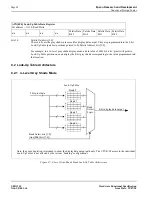
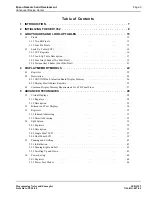
8.2.2 16-Level Gray Shade Mode
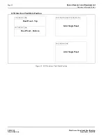
Figure 28: 16-Level Gray-Shade Mode Look-Up Table Architecture
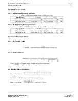
8.3 Power Save Modes (PSM 1)
Two software-controlled Power Save Modes have been incorporated into the SED1352 to accommodate the important need
for power reduction in the hand-held devices market. These modes can be enabled by setting the 2 Power Save bits
(AUX[03h] bits 7-6).
The various settings are:
8.3.1 Power Save Mode 1 (PSM1)
Power Save Mode 1 has two states. Initially when set, the SED1352 enters State 1. If no valid memory cycle is detected
within 1, 2, or 4 clocks (input clock frequency dependent), the chip will enter State 2. The number of clocks of inactivity
before entering State 2 is dependent on the display memory interface and the number of gray shades.
State 1
•
I/O read/write of all registers allowed
•
Memory read/write allowed
•
LCD outputs are either forced low (AUX[03h] bit 5=0), or high impedance (AUX[03h] bit 5=1)
State 2
The same as State 1 as well as:
•
Master clock for display memory access is disabled
Once a valid memory read/write cycle is detected, the SED1352 returns to State 1 where the MPU access is serviced. The
transition from going from State 2 to State 1 requires 1, 2, or 4 clocks (as described above).
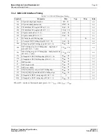
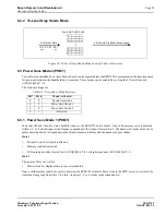
Table 8-5: Power Save Mode Selection
Bit 7 Bit 6
Mode Activated
0
0
Normal Operation
0
1
Power Save Mode 1
1
0
Power Save Mode 2
1
1
Reserved
4 bit pixel data
( P3, P2, P1, P0 )
4 bit Look-Up Table data output
msb
lsb
Look-Up Table 16x4
0
1
2
3
C
D
E
F