


Page 14
Epson Research and Development
Vancouver Design Center
SED1352
SDU1352B0C Rev. 1.0 Evaluation Board User Manual
X16-AN-002-09
Issue Date: 98/10/07
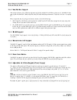
1.3.7 Adjustable LCD Panel Positive Power Supply
Most single Monochrome 640x480 STN LCD panels require a positive power supply to provide b23V and +40V
(I
out
=45mA). For ease of implementation, such a power supply has been provided as an integral part of this design. The
signal VDDH can be adjusted by R8 (100K potentiometer) to provide an output voltage from +23 V to +40 V and is
enabled/disabled by the control signal LCDENB.
Note
LCDENB is directly controlled by register AUX[01], bit 4, of the SED1352. The VDDH power supply used on the
SDU1352 requires a logic “1” to disable it. As the signal LCDENB is a logic “0” at power-up, it is inverted by ex-
ternal logic to disable VLCD and prevent damaging the panel connected to the SDU1352.
Determine the panel’s specific power requirements and set the potentiometer accordingly before connecting the panel.
1.3.8 Crystal Support
The input crystal frequency may be up to 25.175MHz depending on the specific panel size and frame rate desired.
Refer to Section 9.3 of the SED1352 Functional Specification, Drawing Office No. X16-SP-001-xx for further details.
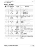
1.3.9 CPU/Bus Interface Header Strips
All of the CPU/Bus interface pins of SED1352 are connected to the header strips H1 and H2 for easy interface to a
CPU/Bus other than the ISA bus.
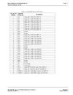
Refer to Table 1-5, “CPU/BUS Connector H1 Pinout,” on page 10 and Table 1-6, “CPU/BUS Connector H2 Pinout,” on
page 11 for specific settings.
Note
These headers only provide the CPU/Bus interface signals from SED1352, when MC68K interface is selected (SW1-3
closed), external decoding logic MUST be used to access the SED1352.
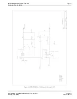
1.3.10 Schematic Notes
The evaluation boards may have been modified and therefore the following schematics may not reflect the actual imple-
mentation. Please request updated information before starting any hardware design.