


Page 12
Epson Research and Development
Vancouver Design Center
SED1352
SDU1352B0C Rev. 1.0 Evaluation Board User Manual
X16-AN-002-09
Issue Date: 98/10/07
1.3 Technical Description
1.3.1 ISA Bus Support
This board directly supports the 16-bit and 8-bit ISA Bus with indexing I/O via a standard AT edge connector.
External logic has been added to provide signals which the SED1352 does not support directly. See Application Note
X16-AN-003-xx.
Note
1. This board has been designed to operate in conjunction with either a VGA card or monochrome card, or as a stand-
alone card.
If using the SDU1352B0C in conjunction with a VGA display adapter the following limitations apply:
a. Only 64K bytes of memory is available, residing at the D000h segment.
b. Given the memory limitation certain panel size and gray shade capabilities are reduced.
c. The VGA card video BIOS must be 8-bit only.
The SDU1352B0C must be configured as follows:
SW1-1 open
: 8-bit operation, necessary to prevent MEMCS16# conflict when reading VGA BIOS
SW1-2 to 7
: set as desired
SW1-8 closed
: 64K bytes available at D000h segment
JP1 2-3 shorted
: to reflect SW1-8 polarity
If using the SDU1352B0C in conjunction with a monochrome display adapter all 128K bytes of memory is available
residing at segment C000h - D000h.
The SDU1352B0C can be used as a stand-alone video adapter with 128K bytes memory available. If used as a stand-
alone video adapter the BIOS setup program for the computer must support and have “No Video” selected as the vid-
eo adapter. The BIOS1352.COM utility program can be used with the evaluation board to simulate a standard video
BIOS, thus providing text and cursor functionality. See the BIOS1352.COM Utility manual, X16-UI-003-xx for de-
tails.
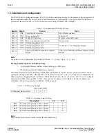
2. This board is pre-set to use indexing I/O with address 000 0011 0??? 000x, where x is don’t care and ??? can be
configured through dip-switch SW1-7 to SW1-5. The factory setting of ??? = 001, i.e., I/O address = 0310h and
0311h.
3. In indexing I/O, only two I/O address spaces are needed. For example, if I/O address 310h is used, 310h will be the
index register and 311h will be the data register.
Example:
I/O write 310h 01
:set index = 1
I/O read 311h
:read contents of AUX[01h]
I/O write 310h 05
:set index = 5
I/O write 311h 07
:write 07 to AUX[05h]