


Epson Research and Development
Page 53
Vancouver Design Center
Hardware Functional Specification
SED1352
Issue Date: 99/07/28
X16-SP-001-16
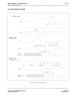
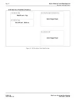
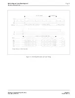
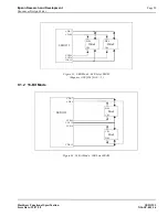
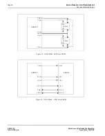
In 8-bit memory interface, if the Address Pitch Adjustment is not equal to zero, then a virtual screen with a
line length of (Line Byte Count +AUX[0Dh]+1) bytes is created, with the display reflecting the contents of
a window (Line Byte Count+1) bytes wide. The position of the window on the virtual screen is determined
by AUX[06h] and [07h], and AUX[08h] and [09h].
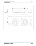
In 16-bit memory interface, if the Address Pitch Adjustment is not equal to zero, then a virtual screen with
a line length of 2(Line Byte Count +AUX[0Dh]+1) bytes is created, with the display reflecting the con-
tents of a window 2(Line Byte Count+1) bytes wide. The position of the window on the virtual screen is
determined by AUX[06h] and [07h], and AUX[08h] and [09h].
.
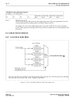
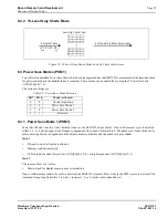
The SED1352 has one internal 16 position, 4-bit wide Look-Up Table (palette). The 4-bit value programmed into each table
position determines the output gray shade/weighting of display data.
The Look-Up Table can be arranged in two different configurations. Refer to Table 27, “4-Level Gray-Shade Mode Look-
Up Table Architecture,” on page 54 for formats.
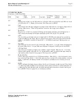
bits 7-6
Bank Bits [1:0]
In 4-level gray mode (2-bits/pixel), the 16 position palette is arranged into four, 4 position “banks”. These
two bits control which bank is currently selected. These bits have no effect in 16-level gray mode (4-
bits/pixel).
bits 5-4
ID Bits
After power on or hardware reset, these bits can be read to identify the current revision of the SED1352.
These same bits are used to identify the pin compatible SED1352F0x and would only be used in system
implementations where common software is utilized. As these bits are R/W they must be read before being
written in order to be used as ID bits.
bits 3-0
Palette Address Bits [3:0]
These 4 bits provide a pointer into the 16 position Look-Up Table currently selected for CPU R/W access.
Note
The Look-Up Table configuration (e.g. 1/2 banks) does not affect the R/W access
from the CPU as all 16 positions can be accessed sequentially.
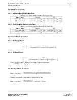
AUX[0Eh] Look-Up Table Address Register
I/O address = 1110b, Read/Write
Bank
Bit 1
Bank
Bit 0
ID Bit
(Read Only)
ID Bit
(Read Only)
Palette
Address
Bit 3
Palette
Address
Bit 2
Palette
Address
Bit 1
Palette
Address
Bit 0
Table 8-4: ID Bit Usage
Chip
Aux[0Eh]
bit 5
bit 4
Power On
or
RESET
SED1353
0
0
F352
0
1
SED1352F0B/F1B/D0B
1
0
SED1352F0A
1
1